EasyManua.ls Logo

Yamaha DTP901 User Manual

Yamaha DTP901
91 pages
To Next Page IconTo Next Page
Page #1 background imageLoading...
Page #1 background image
SERVICE MANUAL
HAMAMATSU, JAPAN
DTP900: 20100310-126000
DTP901: 20100310-195300
DTP902: 20100310-241500
ED
011977
You must have a PCY135/PCY155 service manual
(ED
011894
) before servicing the PCY135/PCY155.
You must have a RHH135 service manual
(ED
011895
)
before servicing the RHH135.
You must have a KP125W service manual
(ED
011971
)
before servicing the KP125W.
You must have a XP120SD/XP100SD service manual
(ED
011969
)
before servicing the XP120SD.
You must have a XP120T/XP100T service manual
(ED
011970
)
before servicing the XP120T/XP100T.
Copyright (c) Yamaha Corporation. All rights reserved. PDF
&
’10.03
DTX900K ....................................................................... 2
DTX950K ....................................................................... 2
COMPLETE ASSEMBLY(同梱品セット) .................... 3
PARTS LIST(パーツリスト) .................................... 4
CONTENTS(目次)
PCY135/PCY155 は、
PCY135/PCY155 (ED
011894
) のサービスマニュアル
をご覧ください。
RHH135 は、RHH135
(ED
011895
)
のサービスマニュアルをご覧ください。
KP125W アフターサービス実施時には、KP125W
(ED
011971
)
のサービスマニュアルをご覧ください。
XP120SD のアフターサービス実施時には、XP120SD/
XP100SD
(ED
011969
)
のサービスマニュアルをご覧
ください。
XP120T/XP100T のアフターサービス実施時には
XP120T/XP100T
(ED
011970
)
のサービスマニュアル
をご覧ください。
DTP900/DTP901/DTP902
• PCY135 • PCY155
• KP125W
• RHH135
• XP100T • XP120T
• XP120SD
●
PCY135
●
PCY155
●
RHH135
●
KP125W
●
XP120SD
●
XP100T
●
XP120T
• DTX900K
• DTX950K
w
w
w
.
x
i
a
o
y
u
1
6
3
.
c
o
m
Q
Q
3
7
6
3
1
5
1
5
0
9
9
2
8
9
4
2
9
8
T
E
L
1
3
9
4
2
2
9
6
5
1
3
9
9
2
8
9
4
2
9
8
0
5
1
5
1
3
6
7
3
Q
Q
TEL 13942296513 QQ 376315150 892498299
http://www.xiaoyu163.com
RS130 (Rack System
HXR4LD (Rack System
Question and Answer IconNeed help?

Do you have a question about the Yamaha DTP901 and is the answer not in the manual?

Yamaha DTP901 Specifications

General IconGeneral
BrandYamaha
ModelDTP901
CategoryDrums
LanguageEnglish

Summary

KP125W Electronic Drum Pad Service Manual

SPECIFICATIONS

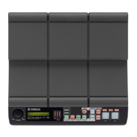
Technical specifications for the KP125W drum pad.

DISASSEMBLY PROCEDURE

Step-by-step instructions for taking apart the KP125W.

CIRCUIT DIAGRAM

Electrical schematic diagram for the KP125W.

INSPECTION OF FUNCTION

Procedures for testing the KP125W's functionality.

PARTS LIST

Comprehensive list of all replaceable parts for the KP125W.

XP120T/XP100T Electronic Drum Pad Service Manual

SPECIFICATIONS

Technical specifications for XP120T and XP100T drum pads.

DISASSEMBLY PROCEDURE

Step-by-step instructions for disassembling the XP120T/XP100T.

CIRCUIT DIAGRAM

Electrical schematic for the XP120T/XP100T.

INSPECTION OF FUNCTION

Procedures for testing the XP120T/XP100T functionality.

PARTS LIST

List of all parts for the XP120T and XP100T models.

RHH135 Real Hi-Hat Pad Service Manual

SPECIFICATIONS

Technical specifications for the RHH135 hi-hat pad.

DISASSEMBLY PROCEDURE

Step-by-step guide to disassembling the RHH135.

CIRCUIT DIAGRAM

Electrical schematic for the RHH135.

OUTPUT CHECK (出力確認)

Procedures for verifying pad and rim area output.

3. Checking HI-HAT Control

Details HI-HAT control functionality checks.

HXR4LD Electronic Drum Rack System

SET UP EXAMPLE (セットアップ例)

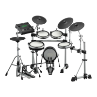
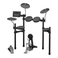
Illustrates the setup of the DTXTREME III Special Set.

COMPLETE ASSEMBLY (同梱品セット)

Lists all parts included in the HXR4LD complete set.

SERVICE PARTS KIT (サービスパーツキット)

Identifies service parts for the HXR4LD rack system.

CROSS CLAMP BODY ASSEMBLY (クロスクランプボディ Ass'y)

Details the cross clamp body assembly parts.

DRUM ARM CLAMP ASSEMBLY (ドラムアームクランプ Ass'y)

Lists parts for the drum arm clamp assembly.

RS130 Electronic Drum Rack System

SET UP EXAMPLE (セットアップ例)

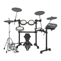
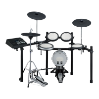
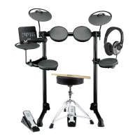
Shows the standard setup for the DTXTREME III.

OVERALL ASSEMBLY (総組立)

Exploded view and parts list for the overall RS130 rack assembly.

PILLAR C ASSEMBLY (ピラー C Ass'y)

Parts list and diagram for the Pillar C assembly.

PILLAR L ASSEMBLY (ピラー L Ass'y)

Parts list and diagram for the Pillar L assembly.

PILLAR R ASSEMBLY (ピラー R Ass'y)

Parts list and diagram for the Pillar R assembly.

CENTER PIPE A (センターパイプA)

Parts list and diagram for the Center Pipe A.

MODULE ARM (モジュールアーム)

Parts list and diagram for the Module Arm.

TUBE CLAMP ASSEMBLY (チューブクランプ Ass'y)

Lists parts for the tube clamp assembly.

HOLDER CLAMP ASSEMBLY (ホルダークランプ Ass'y)

Lists parts for the holder clamp assembly.

LEG CONNECTOR ASSEMBLY (レッグコネクター Ass'y)

Parts list and diagram for the leg connector assembly.

TOM HOLDER ASSEMBLY 2 (タムホルダー Ass'y2)

Parts list and diagram for the tom holder assembly.

Related product manuals