26
DTX500 Owner’s Manual
7 Create Your Own Original Drum Kit
The DTX500 lets you create your own original Drum Kit by assigning your favorite Drum Voice to
each pad and setting its tuning, pan, decay, reverb, etc.
*Drum Voice: Mainly individual percussion/drum sounds that are assigned to each of the pads.
*Drum Kit: A collection of Drum Voices assigned to pads.
1
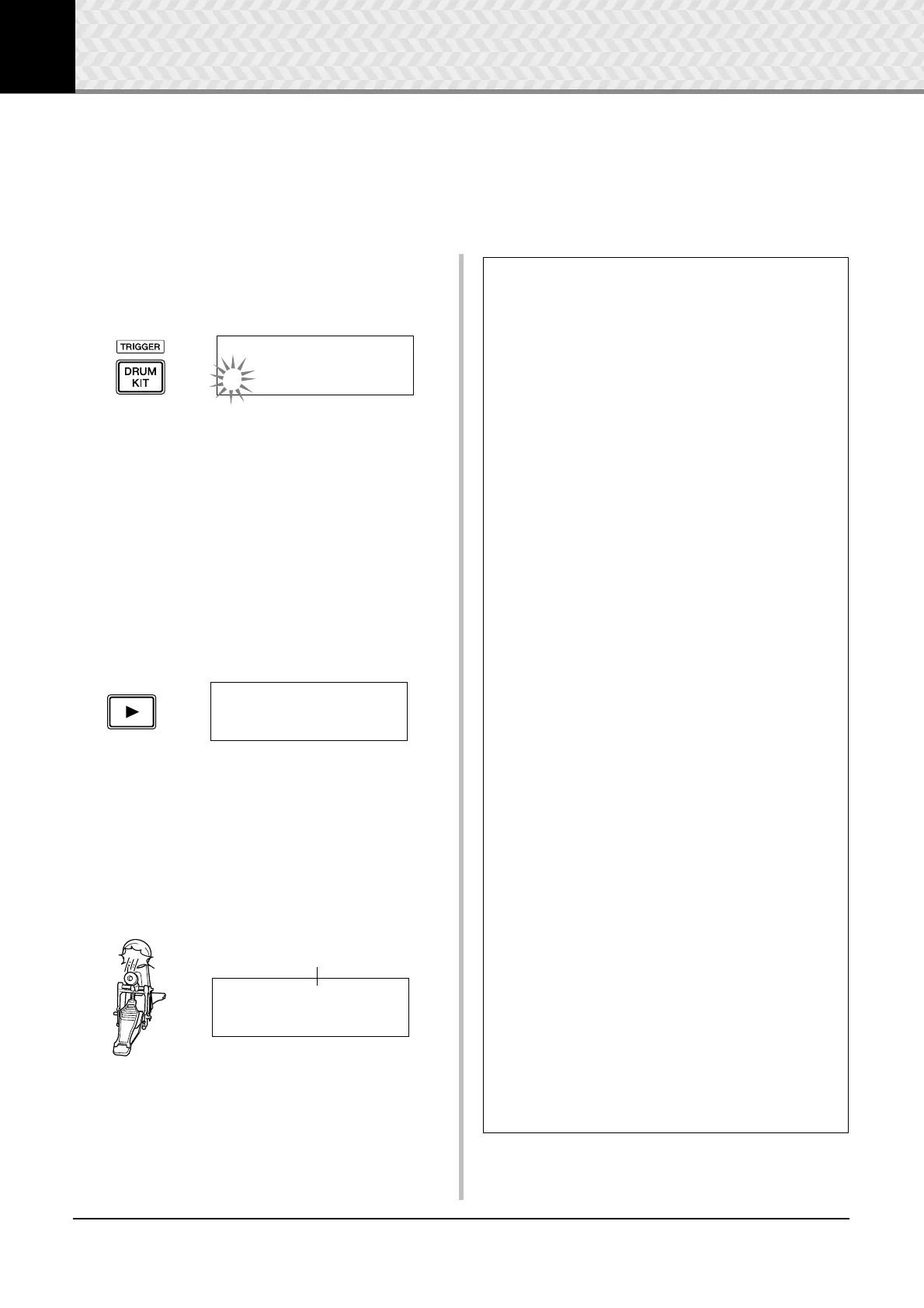
Select a Drum Kit
Press the [DRUM KIT] button to view the Drum Kit Select
display (KIT1).
Rotate the jog dial to select the Drum Kit you want to use as a
starting point for your original Drum Kit. A good idea is to
select a Drum Kit that is close in sound to the type of kit you
intend to create.
* Preset Drum Kits (1–50) and user Drum Kits (51–70) can be
used for editing as well.
2
Assign Drum Voices
In this example, we’ll create a bass drum (kick) sound.
2-1. Press the [
>] button to view the Drum Voice Select
page (KIT2).
2-2. To select the pad (trigger input source) you want to
edit, simply hit the pad you want to edit or use the
[SHIFT] + [
<]/[>] buttons.
Step on the kick pedal or press the [SHIFT] + [<]/
[
>] buttons and select “äkick.” Now the pad that is
connected to the 8KICK Trigger Input Jack is
selected. In other words, the kick pedal’s pad input is
selected.
KIT1~~~ååååååååå
1~:Oak~Custom~~‚
KIT2~~~ƒsnare~~˙
”S01:OakCustom~‚
Pad to be edited
KIT2~~~äkick~~~˙
”K01:OakCustom~‚
● About the Trigger Input Sources
The Input Source indicates the trigger data that is transmitted by the pads
or drum triggers (Yamaha DT20, etc.) that are connected to trigger input
jacks 1SNARE to 8KICK/ 9 of the DTX500.
When mono pads TP65, KP125W/125/65, PCY65/130, DT10/20, etc. are
used, one Input Source is assigned to one input jack. When stereo pads
RHH135/130, PCY65S, etc. are used, two Input Sources (pad input and
rim switch input or 2 kinds of pad inputs, etc.) are assigned to one input
jack.
When three-zone pads XP100T/100SD/120T/120SD, TP65S, TP120SD/
100, PCY155/150S/135/130SC, etc., are used, three Input Sources (pad
input and two rim switch inputs, etc.) will be assigned to one input jack.
Each Input Source is defined as follows.
ƒsnare Pad input for 1SNARE jack.
ƒsnrOp Open rim switch input for 1SNARE jack.
ƒsnrCl Closed rim switch input for 1SNARE jack.
ƒsnrOff Pad input for 1SNARE jack with the snares off.
ƒsnrOfOp Open rim switch input for 1SNARE jack with the
snares off.
ƒsnrOfCl Closed rim switch input for 1SNARE jack with the
snares off.
™tom1 Pad input for 2TOM1 jack.
£tom2 Pad input for 3TOM2 jack.
Ωtom3 Pad input for 4TOM3 jack.
•ride Pad input for 5RIDE jack.
•rideE Edge rim switch input for 5RIDE jack.
•rideC Cup switch input for 5RIDE jack.
öcrash Pad input for 6CRASH jack.
öcrashE Edge rim switch input for 6CRASH jack.
öcrashC Cup switch input for 6CRASH jack.
ühhOp Pad input for 7HI HAT jack when the hi-hat controller
is open.
ühhOpE Edge rim switch input for 7HI HAT jack when the hi-
hat controller is open.
ühhCl Pad input for 7HI HAT jack when the hi-hat controller
is closed.
ühhClE Edge rim switch input for 7HI HAT jack when the hi-
hat controller is closed.
ühhFtCl Input when the hi-hat controller is pressed (foot close).
ühhSplsh Foot splash input of the hi-hat controller.
äkick Pad input for 8KICK jack.
“pad9 Pad input for 8PAD 9 jack.
ƒπpad10 Pad input for 2PAD 0 jack.
ƒƒpad11 Pad input for 3PAD ! jack.
Īpad12 Pad input for 4PAD @ jack.
* Mono pads do not have a rim switch function.