Do you have a question about the Yamaha DVR-S120 and is the answer not in the manual?
| Type | DVD Recorder |
|---|---|
| Video Recording System | MPEG-2 |
| Audio Recording System | Dolby Digital |
| Component Video Output | Yes |
| Composite Video Output | Yes |
| S-Video Output | Yes |
| DVD player type | DVD player |
| Playback Formats | DVD, CD |
| Recording Formats | DVD-R |
| Digital Audio Output | Coaxial |
Explains conditions under which the laser emits and precautions.
Lists properties of the laser diode used in the product.
Details worktable and human body grounding procedures to prevent static damage.
Precautions for handling and testing the optical pickup to prevent damage.
Gentle handling guidelines for the high-precision traverse unit.
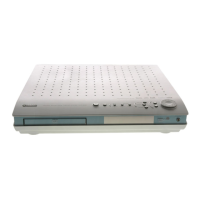
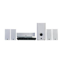
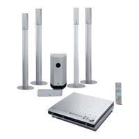
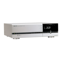
Illustration of the front panel of the DVR-S120 unit.
Diagram of the remote control for J model units.
Diagram of the remote control for U, C, R, T, K, L, A models.
Diagram of the remote control for B, G models.
Rear panel connections for DVR-S120 U, C, R, T, K, L, A models.
Rear panel connections for DVR-S120 B, G models.
Rear panel connections for DVR-S120 J model.
Rear panel diagram for the NX-S120 unit.
Rear panel diagram for the NX-C120 unit.
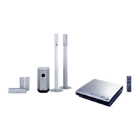
Detailed specifications for the DVR-S120 unit, including amplifier, DVD, video, and tuner sections.
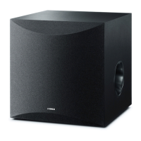
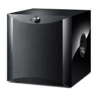
Specifications for the NX-SW120 subwoofer.
Specifications for the NX-C120 center speaker.
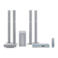
Dimensional drawings for the DVR-S120 unit.
Dimensional drawings for the NX-SW120 subwoofer.
Dimensional drawings for the NX-C120 center speaker.
Dimensional drawings for the NX-S120 speaker.
Internal component layout diagram for the DVR-S120.
Internal component layout diagram for the NX-SW120.
Step-by-step instructions for removing the left and right side covers.
Instructions for removing the bottom cover of the unit.
Instructions for removing the D-Amp Module.
Steps for removing the MAIN (3) P.C.B.
Procedure for removing the AM/FM Tuner.
Instructions for removing the MAIN (1) P.C.B.
Procedure for removing the front grille of the NX-SW120.
Steps for removing the rear panel of the NX-SW120.
Table listing DIAG menu items and their corresponding sub-menus for self-diagnosis.
Describes the display when no protection history is recorded.
Explains how protection function history is displayed.
Lists functions that can be operated while the DIAG menu is active.
Describes the default settings applied when starting the DIAG function.
Explains the DSP Through function and its sub-modes like ANALOG BYPASS.
Details the YSS 0dB mode, including head margin output.
Explains the YSS Front 0dB mode, including head margin output.
Table showing analog switch settings for different sub-menus within SPEAKERS SET.
Details the settings and output for the MAIN 12dB MARGIN mode.
Details the settings and output for the MAIN 18dB MARGIN mode.
Output of noise from all channels except SUB WOOFER.
Output of noise from the FRONT L channel.
Output of noise from the CENTER channel.
Output of noise from the FRONT R channel.
Output of noise from the SURROUND R channel.
Output of noise from the SURROUND L channel.
Output of noise from the SUB WOOFER channel.
Protects user settings by preventing RAM initialization.
Reserves RAM initialization and allows resetting to factory settings or clearing protection history.
Table showing factory preset data for FM and AM stations.
Shows power supply voltage protection values and their normal ranges.
Checks the A/D function of panel keys and explains how to navigate sub-menus.
Tests the fan drive function at different levels (HIGH, MID, LOW).
Indicates status information of the microprocessor.
Digital input/output setting value, REC OUT/INPUT selection.
Fs information of reproduction signal.
Audio code mode information of reproduction signal.
Format information of reproduction signal.
Channel status information of input signal (IEC60958), not used.
Bit stream information in DOLBY DIGITAL signal, not used.
Bit stream information in dts signal, not used.
Device status information of YSS938, not used.
Unsolicited messages from CS49329, not used.
Mute Trigger function, not used in this model.
Checks YSS938 bus connection status (WAIT, NoEr, DATA, RSCS, ADDR).
Checks PLD/SRAM bus connection status (WAIT, NoEr, DATA, EDxx, EAxx).
Shows microprocessor version information.
Displays the checksum for the entire program area.
Checks microprocessor function port settings.
Shows the AAC function detection port status.
Displays the software date.
Indicates the presence or absence of ROM correction data.
Displays the checksum of the ROM correction area.
Shows ROM collection data reception via remote control.
Allows checking the received remote control code.
Allows reserving or canceling the deletion of protection history.
Selects HIGH or LOW output for UCD clock using A/B/C/D/E keys.
Selects H, M, or L output for aspect and interlace/progressive ports.
Table showing pin connections for the pattern area.
Diagram showing grid assignments for various functions.
Pin details and functions for the main CPU IC381.
Details key input pull-up resistors and their corresponding display values.
Tuning market and DVD region select pull-up resistors.
Conditions required before performing adjustments.
Procedure to adjust DC offset voltage on D-Amp modules.
Block diagram for the DIGITAL section of the DVR-S120.
Block diagram for the SUB section of the DVR-S120.
Block diagram for the MAIN section of the DVR-S120.
Foil side layout of the DVD mechanism PCB.
Foil side layout of the MAIN (1) P.C.B.
Foil side layout of the DVD-S120 PCB.
Foil side layout of the MAIN (1) P.C.B.
Foil side layout of the MAIN (2) P.C.B.
Foil side layout of the MAIN (1) P.C.B.
Layout of MAIN (2) CB124 connections.
Layout of the power transformer.
Layout of the D-AMP module.
Foil side layout of the MAIN (1) P.C.B.
Foil side layout of the MAIN (3) P.C.B.
Foil side layout of the MAIN (1) P.C.B.
Foil side layout of the SUB (1) P.C.B.
Foil side layout of the SUB (2) P.C.B.
Foil side layout of the SUB (1) P.C.B.
Foil side layout of the SUB (2) P.C.B.
Foil side layout of the SUB (3) P.C.B.
Foil side layout of the SUB (4) P.C.B.
Printed circuit board layout for the NX-SW120 MAIN (1).
Printed circuit board layout for the NX-SW120 MAIN (2).
Schematic diagram for the Audio Part (part 3 of 5).
List of electrical components with part numbers and descriptions.
List of chip carbon resistor values and part numbers.
Remote control button mapping and codes for the J model.
Remote control button mapping and codes for U, C, R, T, K, L, A models.
Remote control button mapping and codes for B, G models.