GEN
INFO
General information
1-9
69J3D11
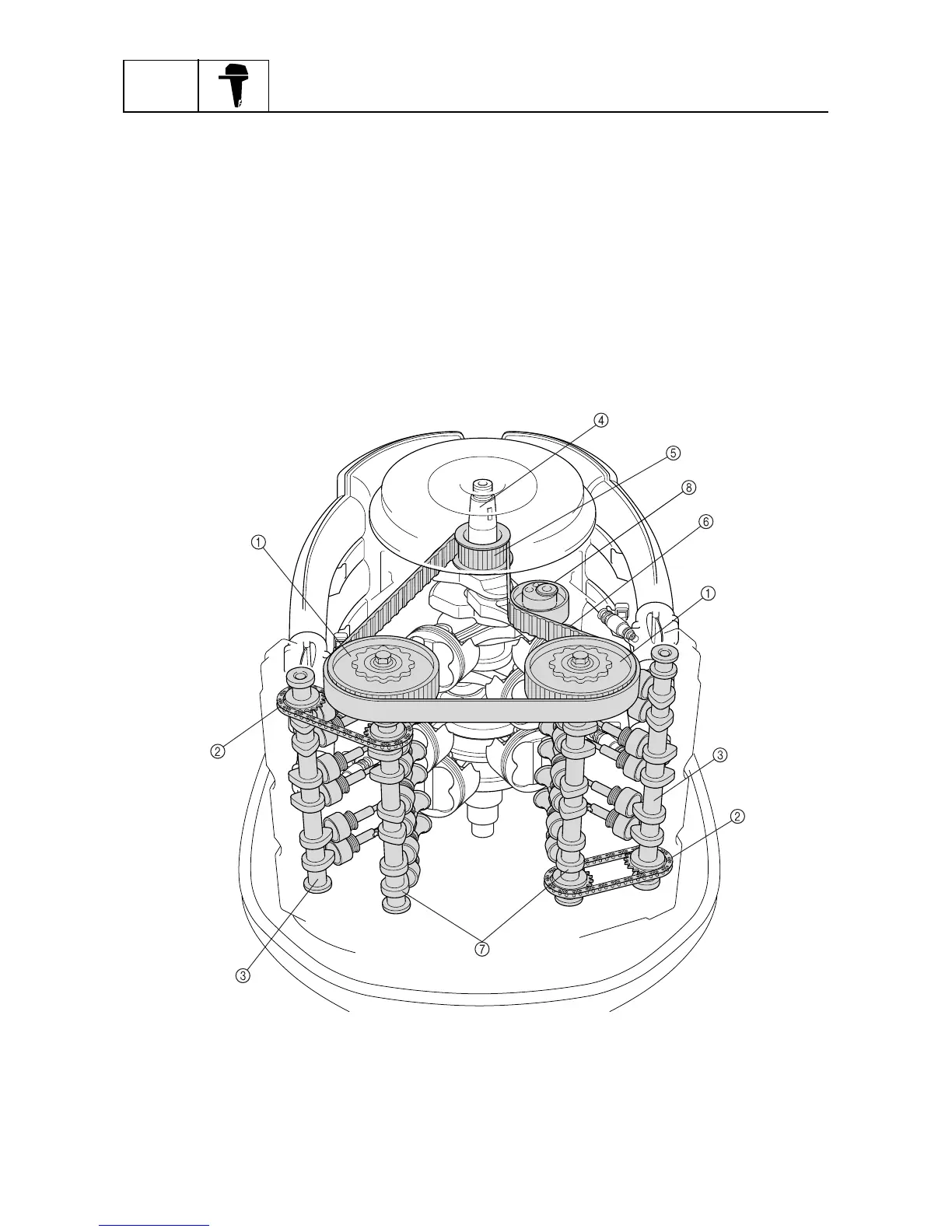
Valve train system
The valve train consists of a total of four camshafts, with two in each bank.
The camshafts are driven with the combination of a belt and chains. The crankshaft turns the belt to
drive the exhaust camshafts in both banks. Chains connect the exhaust camshafts to the intake
camshafts in the cylinder heads to drive the intake camshafts.
In addition, the timing belt offers quieter operation, and the cam chains help to achieve a compact
configuration through the use of individual driven sprockets.
Timing belt
The timing belt, which is driven by the drive sprocket that is attached to the crankshaft, rotates the
driven sprockets that are attached to the exhaust camshafts of both banks. The drive sprocket for
the timing belt is secured to the crankshaft by four bolts, and it can be removed easily for servicing.
In addition, the material of the driven sprockets has been changed from the previous metal to plastic
for weight reduction.
1
Driven sprocket
2
Timing chain
3
Intake camshaft
4
Crankshaft
5
Drive sprocket
6
Timing belt
7
Exhaust camshaft
8
Hydraulic timing belt tensioner
S69J1290
 Loading...