0-4
0
How to use this manual
Manual format
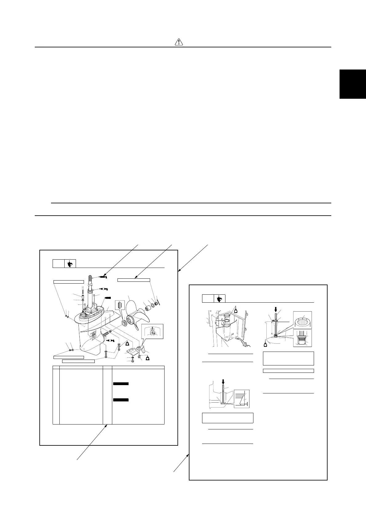
The format of this manual has been designed to make service procedures clear and easy to under-
stand. Use the following information as a guide for effective and quality service.
• Parts are shown and detailed in an exploded diagram and are listed in the component list (see 1
in the following figure for an example page).
• The component list consists of part names and quantities, as well as bolt and screw dimensions
(see 2 in the following figure).
• Symbols are used to indicate important aspects of a procedure, such as the grade of lubricant and
the lubrication points (see 3 in the following figure).
• Tightening torque specifications are provided in the exploded diagrams (see 4 in the following fig-
ure), and in the related detailed instructions. Some torque specifications are listed in stages as
torque figures or angles in degrees.
• Separate procedures and illustrations are used to explain the details of removal, checking, and
installation where necessary (see 5 in the following figure for an example page).
TIP:
For troubleshooting procedures, see Chapter 4, “Troubleshooting.”
LOWR
Lower unit
8-1
Lower unit
No.
Part name Q’ty Remarks
1tun gnitsujdA1
1tunkcoL2
2lewoD3
1wercs kcehC4
2teksaG5
Not reusable
1wercs niarD6
4rehsaW7
01M4tloB8 × 35 mm
1edonA9
1rehsaw laicepS01
Not reusable
6M1tloB11 × 35 mm
6M1tloB21 × 18 mm
1bat mirT31
1tinu rewoL41
1recapS51
1relleporP61
1ralloC71
3
1
2
3
6
5
5
4
20
19
18
17
15
16
14
13
12
11
10
9
8
7
518
M
A
D
LT
572
LT
LT
572
LT
1901
9 N
·
m (0.9 kgf
·
m, 6.6 ft
·
Ib)
9 N
·
m (0.9 kgf
·
m, 6.6 ft
·
Ib)
34 N
·
m (3.4 kgf
·
m, 25.1 ft
·
Ib)
37 N
·
m (3.7 kgf
·
m, 27.3 ft
·
Ib)
LOWR
Lower unit
8-17
TIP:
Do not reuse a shim if deformed or
scratched.
3. While holding the special service tool 3,
strike the tool to check that the taper
roller bearing outer race is installed prop-
erly.
TIP:
If a high-pitched metallic sound is produced
when the special service tool is struck, the
taper roller bearing outer race 2 is installed
properly.
4. Install a new needle bearing 5 to the
specified depth a.
TIP:
• Face the identification mark b on the nee-
dle bearing toward the water pump side.
• Install the stopper c onto the driver rod 6
at the specified depth a.
5. Heat the installation area of the taper
roller bearing outer race in the lower
case using a gas torch, and then install
the sleeve 9, the original pinion shims
0, and a new taper roller bearing outer
race A.
NOTICE:
When heating the
lower case, heat the entire installation
area evenly. Otherwise, the paint on
the lower case could be burned.
Driver rod LL 3: 90890-06605
Bearing outer race attachment 4:
90890-06625
1
2
G
3
2
1
3
Driver rod SL 6: 90890-06602
Bearing depth plate 7: 90890-06603
Needle bearing attachment 8:
90890-06615
Depth a: 185.0–186.0 mm (7.28–7.32 in)
a
c
5
7
6
G
b
4
7
2
5
34 1
Safety while working / How to use this manual

 Loading...