Do you have a question about the Yamaha F30B 2018 and is the answer not in the manual?
Distinguishes key safety and operational notations like WARNING, NOTICE, and TIP.
Provides details about applicable models and their designations.
Outlines critical safety precautions and guidelines for servicing the equipment.
Explains the manual's format, symbols, and conventions for effective service.
Details general and specific tightening torque values for fasteners.
Illustrates symbols used to identify specifications and components.
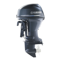
Provides external dimensions for F30BEHD and F30EHA models.
Displays external dimensions for the F30HA model.
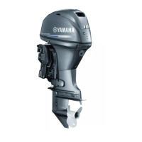
Shows external dimensions for F30BET and F30A models.
Illustrates external dimensions for F40FEHD and F40EHA models.
Presents external dimensions for the F40HA model.
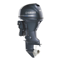
Details external dimensions for the F40FED model.
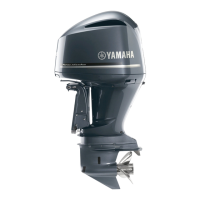
Provides external dimensions for F40FET and F40A models.
Explains the electronic control system, including ECM, sensors, and actuators.
Details the Engine Control Module (ECM) and its role in engine control.
Describes the intake silencer and its function in engine operation.
Outlines the components and diagrams of the fuel system.
Details the lubrication system and its associated diagrams.
Explains the cooling system and provides a cooling diagram.
Describes the intake and exhaust systems with diagrams.
Illustrates the routing of various hoses for fuel, vapor, and cooling systems.
Provides critical warnings and instructions before rigging the outboard motor.
Gives instructions on how to handle the crate containing the outboard motor.
Provides step-by-step instructions for safely uncrating the outboard motor.
Details the process of mounting rigging grommets for cables and harnesses.
Explains the installation procedure for the tiller handle.
Emphasizes proper battery connection and cable sizing to prevent fires.
Guides selection of the correct propeller based on engine speed and boat load.
Introduces the Yamaha Diagnostic System (YDIS) and explains CAN-Line connection.
Explains the K-Line connection setup for the YDIS using a laptop.
Outlines general troubleshooting steps, pre-checks, and YDIS usage for power unit issues.
Lists recognized trouble codes, items, and detailed checking steps.
Provides procedures for diagnosing issues when specific trouble codes are absent.
Guides troubleshooting for engine cranking, starting, spark, fuel, and compression issues.
Details troubleshooting steps for PTT unit operation, fluid pressure, and motor issues.
Guides troubleshooting for the lower unit's gear shift mechanism and related components.
Illustrates the layout and routing of electrical components and wire harnesses on the port side.
Presents a detailed circuit diagram for the Engine Control Module (ECM) with terminal numbers.
Provides a visual representation and list of ECM coupler connections and their colors.
Details methods for checking electrical components using YDIS and peak voltage measurements.
Covers checks for main relays, ECM circuits, TPS, and starter components.
Explains checks for alert buzzer, trolling switch, water detection switch, and fuel injectors.
Guides checking lighting coil output voltage/resistance and rectifier/regulator voltage/continuity.
Details checks for ignition spark, ECM output voltage, ignition coil resistance, and pulser coil.
Covers checks for starter relays and engine start switch continuity.
Covers reducing fuel pressure, disconnecting connectors, and measuring fuel pressure.
Details fuel filter removal, checking for leaks, and assembly procedures.
Guides checking the fuel pump assembly for leaks and specified pressures.
Covers checking and installing intake silencer, manifold, and throttle body components.
Provides steps for installing and adjusting the throttle link rod.
Details draining fuel, removing, installing, and checking the vapor separator.
Illustrates the fuel cooler assembly and lists all components.
Covers checking fuel strainer, adjusting float height, and assembling the vapor separator.
Explains removing, checking, and installing the fuel injector and related parts.
Covers checks for compression pressure, oil pressure, and related components.
Details checking and adjusting the pulser coil air gap with safety warnings.
Explains measuring and adjusting valve clearances for engine cylinders.
Illustrates the power unit assembly and guides its removal and installation.
Explains removing, checking, and installing the flywheel magneto and timing belt.
Covers mounting procedures for the engine ECM, rectifier/regulator, and ignition coils.
Details the installation of various wire harnesses, clamps, and connectors.
Guides the installation of the starter motor, lead, nuts, and bolts.
Details removing and installing the cylinder head, cover, and bolts with specific torque values.
Covers camshaft and valve disassembly, checking, and replacement procedures.
Details removing, checking, and installing the exhaust cover, oil filter, and thermostat.
Illustrates the cylinder block assembly and guides disassembly, checking, and assembly of components.
Guides removing the lower unit, checking the propeller, and inspecting the anode.
Details checking the water pump housing, impeller, and keyway for wear or deformation.
Explains removing, disassembling, checking, and assembling the propeller shaft housing.
Covers removing, disassembling, and checking drive shaft, forward gear, and lower case components.
Provides workflow and methods for shimming gears, measuring backlash, and selecting shims.
Illustrates the friction plate assembly and lists all components.
Details assembling the tiller handle, including throttle shaft, bushings, and control links.
Illustrates electrical components for tiller handle models and guides assembly.
Illustrates the shift rod and shift bracket assembly and lists all components.
Illustrates the bottom cowling assembly and lists all components.
Covers removing and installing the upper case assembly and its mounting hardware.
Guides checking and assembling the oil pan and exhaust guide components.
Details removing and installing the steering arm, yoke, and related parts.
Covers removing, checking, and installing the hydro tilt assembly with safety warnings.
Details removing, bleeding, and installing the PTT unit, including fluid level checks.
Covers checking clamp bracket anode and adjusting the trim sensor cam.
Details removing, disassembling, checking, assembling, and installing the PTT motor.
Covers checking the gear pump, housing, filter, and valve seal for proper function.
Details removing, checking, and assembling the PTT cylinder and piston.
Provides an overview of maintenance recommendations, interval charts, and operating conditions.
Outlines essential checks for engine oil, battery, cooling water, and switches before delivery.
Details periodic maintenance tasks for various engine and system components.
Presents dimension and weight data for various outboard motor models.
Lists performance specs like rated power, operating range, and power unit details.
Provides technical data for ignition, starting, charging, and fuel systems.
Lists specifications for TPS, oil pressure, trim sensor, and PTT system.
Provides specifications for cylinder head warpage and camshaft dimensions.
Lists technical data for the lower unit, including backlash and shim thicknesses.
Provides technical data for the PTT system, including hydraulic pressure and motor specifications.
Explains how to interpret wiring diagrams, including symbols and terminal numbering.
Shows the wiring diagram for the engine control, fuel, and ignition systems.
Depicts the wiring diagram for charging, starting, and PTT systems.
Shows wiring diagrams for tiller handle and hydro tilt control units.
Provides a table for selecting pinion shims (T3) based on measurement and stamped values.
Shows a chart for selecting forward gear shims (T1) based on backlash measurements.
Provides a chart for selecting reverse gear shims (T2) based on backlash measurements.
| Brand | Yamaha |
|---|---|
| Model | F30B 2018 |
| Category | Outboard Motor |
| Language | English |