7-4
Power unit (check and adjustment)
0
1
2
3
4
5
6
7
8
9
10
A
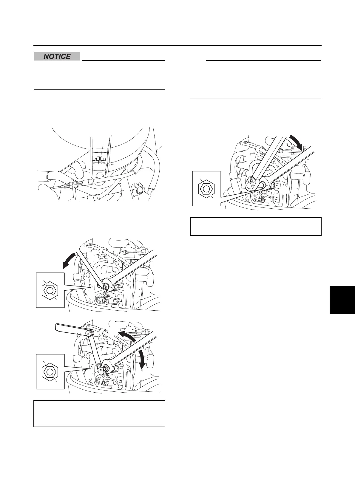
Do not turn the flywheel magnet counter-
clockwise. Otherwise, the water pump
impeller could be damaged.
1. Align the TDC mark a on the flywheel
magnet and the pointer b of the manual
starter.
2. Loosen the valve adjusting locknut a,
and then turn the rocker arm pivot b until
the specified valve clearance is obtained.
• To decrease the valve clearance, turn the
rocker arm pivot in direction c.
• To increase the valve clearance, turn the
rocker arm pivot in direction d.
3. Tighten the valve adjusting locknut a to
the specified torque, and then check the
valve clearances.
Valve clearance:
Intake and exhaust:
0.08–0.12 mm (0.003–0.005 in)
a
b
a
a
b
b
c
d
a
a
b
b
Valve adjusting locknut a:
10 N·m (1.0 kgf·m, 7.4 ft·lb)