Do you have a question about the Yamaha FJR1300(S) and is the answer not in the manual?
Introduces the supplementary manual and lists related service manuals for complete procedures.
Explains the manual's intended use by qualified mechanics and notes on potential changes.
Defines symbols and terms (WARNING, CAUTION, NOTE) used for important information.
Details the organization of the manual into chapters, sections, and sub-sections.
Explains how to interpret symbols used in diagrams and text for procedures.
Lists symbols indicating chapter subjects and general technical information.
Defines symbols for types of lubricants and procedural actions like applying Loctite.
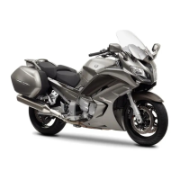
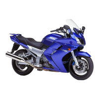
Overview of the motorcycle's key features and systems.
General description of the motorcycle's main functions and systems.
Introduction to the Fuel Injection (FI) system and its benefits.
Lists general model codes and specifications for different regions.
Details specifications for the fuel pump, throttle bodies, and fuel injectors.
Details ignition system type, timing, and coil resistance.
Lists specifications for starter and fuel injection system relays.
Explains the importance of preventive maintenance for reliable operation and service life.
Provides a schedule for checks and lubrication based on odometer readings.
Illustrates and lists parts associated with the fuel tank assembly.
Step-by-step instructions for safely removing the fuel tank.
Procedure for disassembling and removing the air filter case and its components.
Lists and illustrates the various sensors and components of the FI system.
Electrical schematic showing the wiring for the FJR1300 model.
Electrical schematic showing the wiring for the FJR1300A model.
Table detailing fault codes, symptoms, and probable causes for self-diagnostics.
Explains the motorcycle's fail-safe actions in response to sensor malfunctions.
Provides a table to verify sensor data displayed on the meter for diagnostics.
Details inspection and countermeasure steps for specific self-diagnostic fault codes.
Step-by-step guide for removing the throttle body assembly.
Procedure for safely disconnecting and removing fuel injectors.
Instructions for correctly installing the reed valves in the air induction system.
Identifies and illustrates various electrical parts of the motorcycle.
Detailed electrical circuit diagram for the FJR1300 model.
Detailed electrical circuit diagram for the FJR1300A model.
Procedure for verifying the fuel pump's operation and flow.
Lists wire colors and their corresponding codes for the FJR1300 wiring diagram.
Lists wire colors and their corresponding codes for the FJR1300A wiring diagram.
| Engine Type | Liquid-cooled, 4-stroke, DOHC, inline 4-cylinder |
|---|---|
| Displacement | 1298 cc |
| Bore x Stroke | 79.0 mm x 66.2 mm |
| Compression Ratio | 10.8:1 |
| Transmission | 6-speed |
| Final Drive | Shaft |
| ABS | Standard |
| Traction Control | Standard |
| Front Tire | 120/70 ZR17 |
| Rear Tire | 180/55 ZR17 |
| Wheelbase | 1, 545mm |
| Fuel Capacity | 25 liters |
| Fuel System | Fuel Injection |
| Ignition | TCI |
| Rear Suspension | Single shock; adjustable preload and rebound damping |
| Front Brakes | Dual 320 mm discs, 4-piston calipers |
| Rear Brakes | 282 mm disc |
| Seat Height | 805 mm / 825 mm |