EasyManua.ls Logo

Yamaha GX-500 Service Manual

Yamaha GX-500
86 pages
To Next Page IconTo Next Page
Page #1 background imageLoading...
Page #1 background image
GX-500/GX-500VCD
GX-500/VCD
100672
SERVICE MANUAL
GX-500
GX-500VCD
MINI COMPONENT SYSTEM
IMPORTANT NOTICE
This manual has been provided for the use of authorized YAMAHA Retailers and their service personnel.
It has been assumed that basic service procedures inherent to the industry, and more specifically YAMAHA Products, are
already known and understood by the users, and have therefore not been restated.
WARNING: Failure to follow appropriate service and safety procedures when servicing this product may result in
personal injury, destruction of expensive components, and failure of the product to perform as specified.
For these reasons, we advise all YAMAHA product owners that any service required should be performed
by an authorized YAMAHA Retailer or the appointed service representative.
IMPORTANT: The presentation or sale of this manual to any individual or firm does not constitute authorization, certifica-
tion or recognition of any applicable technical capabilities, or establish a principle-agent relationship
of any form.
The data provided is believed to be accurate and applicable to the unit(s) indicated on the cover. The research, engineering, and
service departments of YAMAHA are continually striving to improve YAMAHA products. Modifications are, therefore,
inevitable and specifications are subject to change without notice or obligation to retrofit. Should any discrepancy appear to
exist, please contact the distributor's Service Division.
WARNING: Static discharges can destroy expensive components. Discharge any static electricity your body may have
accumulated by grounding yourself to the ground buss in the unit (heavy gauge black wires connect to this
buss).
IMPORTANT: Turn the unit OFF during disassembly and part replacement. Recheck all work before you apply power to the
unit.
CONTENTS
TO SERVICE PERSONNEL .....................................1~2
GX-500 PANELS .......................................................3~4
GX-500VCD PANELS ................................................... 5
SPECIFICATIONS ......................................................... 6
INTERNAL VIEW .......................................................... 7
DISASSEMBLY PROCEDURES ............................ 8~12
VOLUME RANGE ....................................................... 13
SYSTEM CONTROL CHECK .....................................13
TEST MODE ................................................................ 14
SYSTEM TEST MODE ................................................14
RECEIVER TEST MODE ......................................15~16
TAPE TEST MODE ..................................................... 16
CD TEST MODE ......................................................... 17
ALL FUNCTION TEST MODE ....................................18
CD ERROR MESSAGES ............................................ 18
CD STANDARD OPERATION CHART ................19~22
ADJUSTMENTS ....................................................23~25
IC DATA ................................................................26~32
DISPLAY DATA ....................................................33~34
BLOCK DIAGRAM ................................................35~39
PRINTED CIRCUIT BOARD .................................40~62
PIN CONNECTION DIAGRAM ...................................63
SCHEMATIC DIAGRAM .......................................64~71
PARTS LIST ........................................................72~103
GREASE APPLICATION DIAGRAM ................104~105
GX-500 REMOTE CONTROL TRANSMITTER ........ 106
GX-500VCD REMOTE CONTROL TRANSMITTER ....
107
NX-GX500.................................................................. 108
このサービスマニュアルは、エコマーク認定の再生紙を使用しています
ThisServiceManualusesrecycledpaper.
GX-500 is composed of GX-500 and NX-GX500.
GX-500VCD is composed of GX-500VCD and NX-GX500.

Table of Contents

Other manuals for Yamaha GX-500

Question and Answer IconNeed help?

Do you have a question about the Yamaha GX-500 and is the answer not in the manual?

Yamaha GX-500 Specifications

General IconGeneral
BrandYamaha
ModelGX-500
CategoryStereo System
LanguageEnglish

Summary

Service Information and Safety Precautions

Critical Components and Leakage Current Measurement

Information on critical components and verifying insulation after service.

Laser Beam Safety During Servicing

Precautions for eye protection when servicing laser components.

Chemical Content Notice

Warning about hazardous chemicals in product components.

System Overview and Specifications

GX-500 Front Panel and Component Identification

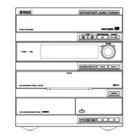
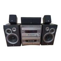
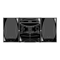
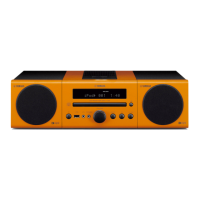
Identification of front panel controls and indicators for GX-500 models.

GX-500 Rear Panel Connections

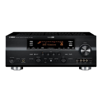
Diagram showing rear panel input/output connections for various models.

GX-500VCD Front Panel, Remote, and Rear Connections

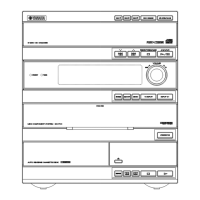
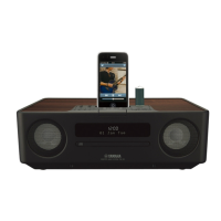
Identification of front panel controls, remote, and rear connections for GX-500VCD.

System Specifications

Detailed technical specifications for amplifier, tuner, tape, CD, and speaker sections.

Internal Structure and Disassembly Procedures

Internal Component Layout Identification

Visual identification of major internal components on top and left sides.

Disassembly Procedures

Step-by-step instructions for disassembling the unit's main components.

Component PCB Checks and Cautions

Procedures for checking CD/VCD and Main PCBs, including cautions.

Tray and Traverse Unit Procedures

Procedures for removing, installing, and precautions for the tray and traverse units.

Test Modes and Adjustments

Volume Range and System Control Check

Details on volume range settings and system control check steps.

Test Mode Overview and Procedures

Explanation of different test modes and their selection procedures.

Receiver, Tape, and CD Test Modes

Details on Receiver, Tape, and CD test mode programs and functions.

Tape Deck Adjustment Procedures

Procedures for mechanical and electrical adjustments of the tape deck section.

Circuit Diagrams and IC Data

IC Data: Signal Processor, CPU, and Pinouts

Information on key ICs, including pinouts and functions.

Block Diagrams

Functional block diagrams illustrating system architecture.

Schematic Diagrams

Detailed circuit schematics for various sections of the unit.

Printed Circuit Boards (PCBs)

PCB Layouts: Tuner, CD, VCD, and Input Sections

PCB layouts for Tuner, CD Player, VCD Player, and Input sections.

PCB Layouts: Operation and Main Sections

PCB layouts for Operation and Main board sections.

Component Lists and Exploded Views

Electrical Components, Abbreviations, and PCB Lists

Lists of electrical components, abbreviations, and detailed PCB parts.

Mechanical Components, Exploded Views, and Accessories

Exploded views and parts lists for mechanical units, accessories, and speakers.

Specific Component Lists (Resistors, Grease)

Specific lists for carbon resistors and grease application diagrams.

Remote Control and Speaker Information

Remote Control Schematics and Button Functions

Schematic diagrams and button function mapping for remote controls.

NX-GX500 Speaker Exploded View and Parts

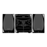
Exploded view and parts list for the NX-GX500 speaker system.

Related product manuals