EasyManua.ls Logo

Yamaha HTR-6064 User Manual

Yamaha HTR-6064
171 pages
To Next Page IconTo Next Page
Page #1 background imageLoading...
Page #1 background image
101214
SERVICE MANUAL
IMPORTANT NOTICE
This manual has been provided for the use of authorized YAMAHA Retailers and their service personnel.
It has been assumed that basic service procedures inherent to the industry, and more speci cally YAMAHA Products, are already known
and understood by the users, and have therefore not been restated.
WARNING:
Failure to follow appropriate service and safety procedures when servicing this product may result in personal injury,
destruction of expensive components, and failure of the product to perform as speci ed. For these reasons, we advise
all YAMAHA product owners that any service required should be performed by an authorized YAMAHA Retailer or
the appointed service representative.
IMPORTANT:
The presentation or sale of this manual to any individual or rm does not constitute authorization, certi cation or
recognition of any applicable technical capabilities, or establish a principle-agent relationship of any form.
The data provided is believed to be accurate and applicable to the unit(s) indicated on the cover. The research, engineering, and service
departments of YAMAHA are continually striving to improve YAMAHA products. Modifications are, therefore, inevitable and
speci cations are subject to change without notice or obligation to retro t. Should any discrepancy appear to exist, please contact the
distributor's Service Division.
WARNING:
Static discharges can destroy expensive components. Discharge any static electricity your body may have
accumulated by grounding yourself to the ground buss in the unit (heavy gauge black wires connect to this buss).
IMPORTANT:
Turn the unit OFF during disassembly and part replacement. Recheck all work before you apply power to the unit.
CONTENTS
TO SERVICE PERSONNEL ............................................2
FRONT PANELS .........................................................3–4
REAR PANELS ...........................................................5–8
REMOTE CONTROL PANELS .......................................9
SPECIFICATIONS ................................................... 10–15
INTERNAL VIEW ..........................................................16
SERVICE PRECAUTIONS ............................................ 17
DISASSEMBLY PROCEDURES ............................. 18–23
UPDATING FIRMWARE ..........................................24–25
SELF-DIAGNOSTIC FUNCTION ............................26–67
CONFIRMATION OF
IDLING CURRENT OF AMP UNIT ....................68
DISPLAY DATA .......................................................69–70
IC DATA ...................................................................71–83
PIN CONNECTION DIAGRAMS .............................84–86
BLOCK DIAGRAMS ................................................87–91
PRINTED CIRCUIT BOARDS ............................... 92–125
SCHEMATIC DIAGRAMS ................................... 127–146
REPLACEMENT PARTS LIST ............................ 147–167
REMOTE CONTROL ........................................... 168–170
ADVANCED SETUP ............................................ 171–172
AV RECEIVER
'11.06
P.O.Box 1, Hamamatsu, Japan
RX-V671/HTR-6064/
RX-A710
RX-V671/HTR-6064/
RX-A710
Note:
When the DIGITAL P.C.B. or IC83 on DIGITAL P.C.B. is replaced, the network function of this unit will not operate
properly without additional setting.
In such a case, report the serial number of this unit to the following e-mail address.
Yamaha Corporation will reply providing the setting procedure to make the network function of this unit operate
properly.
E-mail: ycav-ysiss@gmx.yamaha.com
Copyright © 2011 All rights reserved.
This manual is copyrighted by YAMAHA and may not be copied or
redistributed either in print or electronically without permission.
DRAFT
Question and Answer IconNeed help?

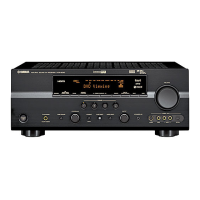
Do you have a question about the Yamaha HTR-6064 and is the answer not in the manual?

Yamaha HTR-6064 Specifications

General IconGeneral
HDMI Inputs4
HDMI Outputs1
Weight9.9 kg
Signal-To-Noise Ratio100 dB
HDMI SwitchingYes
Input Sensitivity200 mV
Audio D/A Converter192kHz/24-bit
DSP Presets17
Tuner BandsAM/FM
Preset Station Qty40
Audio Formats SupportedDolby Digital Plus, Dolby TrueHD
Response Bandwidth10 Hz - 100 kHz
Input Impedance47 kOhm
Tuning RangeFM: 87.5 - 108 MHz, AM: 530 - 1710 kHz
Connector TypeHDMI
Frequency Response10 Hz - 100 kHz
InputsHDMI x 4
Outputs1 HDMI
Supported Audio FormatsWMA, MP3, AAC
Dimensions435 mm

Summary

IMPORTANT NOTICE

TO SERVICE PERSONNEL

Critical Components & Leakage Current

Details on essential components and safety checks for service personnel.

About Lead-Free Solder

Information on the type of solder used and related precautions for repairs.

FRONT PANELS

REAR PANELS

REMOTE CONTROL PANELS

SPECIFICATIONS

Audio Section Specifications

Detailed electrical and performance data for the audio amplifier section.

Video Section Specifications

Detailed electrical and performance data for video input and output signals.

DIMENSIONS

SET MENU TABLE

Speaker Setup Options

Configuration settings for speaker parameters like distance and level.

Video Setup Options

Configuration settings for video signal processing and conversion.

INTERNAL VIEW

SERVICE PRECAUTIONS

Safety Measures During Servicing

Critical safety guidelines, including high voltage warnings and capacitor discharge.

DISASSEMBLY PROCEDURES

Unit Disassembly Steps

Step-by-step instructions for dismantling the RX-V671/HTR-6064 and RX-A710 units.

UPDATING FIRMWARE

Firmware Update Preparation and Tools

Steps for downloading, preparing, and required tools for firmware updates.

Firmware Update Operation Procedures

Step-by-step guide for performing the firmware update via USB.

SELF-DIAGNOSTIC FUNCTION

Audio System Self-Tests

Diagnostic tests for audio signal routing, DSP, speakers, and microphone.

Video and HDMI System Tests

Diagnostic tests for analog/digital video, HDMI, and test patterns.

System Information and Network Tests

Tests for firmware versions, system info, and network connectivity.

Power, Protection, and Keypad Diagnostics

Tests for power protection history and panel key inputs.

Starting Self-Diagnostic Function

Initial Settings for Self-Diagnostic Function

Default settings applied when entering the self-diagnostic mode.

Canceling Self-Diagnostic Function

Display Provided When Self-Diagnostic Function Started

Interpreting Status Messages

Interpretation of status messages and protection indicators during self-diagnosis.

Functions in Self-Diagnostic Function Mode

Operation Procedure of Main Menu and Sub-menu

Details of Self-Diagnostic Function Menu

A1. DSP AUDIO Tests

Detailed explanation of DSP audio diagnostic tests.

A2. DIRECT AUDIO Tests

Detailed explanation of direct audio path diagnostic tests.

A3. HDMI AUDIO Tests

Detailed explanation of HDMI audio path diagnostic tests.

A4. SPEAKERS SET Tests

Detailed explanation of speaker output diagnostic tests.

A7. MANUAL TEST

Diagnostic tests using the built-in noise generator.

D1. FL CHECK Tests

Diagnostic tests for the front panel display.

P1. SYSTEM MONITOR

Tests for power supply status and protection features.

P2. PROTECTION HISTORY

Displays history of protection function triggers for troubleshooting.

S3. FACTORY PRESET

Used to reserve or inhibit initialization of the back-up IC.

S4. ROM VERSION/CHECKSUM

Displays firmware versions and checksums for various components.

CONFIRMATION OF IDLING CURRENT OF AMP UNIT

Check Idling Current Immediately After Power On

Initial measurement of idling current across speaker terminals.

Adjust Idling Current by Cutting Bias Resistors

Procedure for correcting high idling current by adjusting bias resistors.

Confirm Idling Current After 60 Minutes

Final measurement of idling current after stabilization.

DISPLAY DATA

PIN CONNECTION

Details of pin assignments for V4001 on the OPERATION P.C.B.

IC DATA

IC81: R5F6416MADFE (DIGITAL P.C.B.)

Pin details and functions of the main microprocessor.

PIN CONNECTION DIAGRAMS

ICs

Visual representations of IC pinouts for identification.

Diodes

Pin connection diagrams for various diodes.

Transistors

Pin connection diagrams for various transistors.

BLOCK DIAGRAMS

AUDIO Section Block Diagram

Diagram illustrating the audio signal path.

DIGITAL P.C.B. Section Block Diagram

Diagram showing the digital processing signal flow.

NET/USB Section Block Diagram

Diagram showing network and USB signal flow.

VIDEO Section Block Diagram

Diagram illustrating the video signal path.

Power Supply Section Block Diagram

Diagram showing power distribution and regulation.

PRINTED CIRCUIT BOARDS

DIGITAL (1) (Side A) Component Layout

Placement of components on the DIGITAL (1) P.C.B.

OPERATION (1) (Side A) Component Layout

Placement of components on the OPERATION (1) P.C.B.

OPERATION (2) (Side A) Component Layout

Placement of components on the OPERATION (2) P.C.B.

OPERATION (3) (Side A) Component Layout

Placement of components on the OPERATION (3) P.C.B.

OPERATION (8) (Side A) Component Layout

Placement of components on the OPERATION (8) P.C.B.

MAIN (1) (Side A) Component Layout

Placement of components on the MAIN (1) P.C.B.

VIDEO (1) (Side A) Component Layout

Placement of components on the VIDEO (1) P.C.B.

SCHEMATIC DIAGRAMS

DIGITAL Section Schematics

Circuit diagrams for the digital processing units.

OPERATION Section Schematics

Circuit diagrams for the operation boards.

MAIN Section Schematics

Circuit diagrams for the main boards.

VIDEO Section Schematics

Circuit diagrams for the video boards.

REPLACEMENT PARTS LIST

OVERALL ASSEMBLY

RX-V671/HTR-6064 Parts List

Bill of materials for the RX-V671/HTR-6064 unit.

RX-V671/HTR-6064 Front Panel Unit Parts

Replacement parts specifically for the front panel assembly.

RX-V671/HTR-6064 Amp Unit Parts

Replacement parts specifically for the amplifier unit.

RX-A710 Overall Assembly Parts

Bill of materials for the RX-A710 unit.

RX-A710 Parts List - Accessories

Replacement parts for included accessories like remote and cables.

REMOTE CONTROL

REMOTE CONTROL SCHEMATIC DIAGRAM

Circuit diagram of the remote control unit.

REMOTE CONTROL KEY NO. LAYOUT

Diagram showing button numbering and layout on the remote control.

REMOTE CONTROL KEY CODE

Table mapping key codes to functions for different remote models.

ADVANCED SETUP

Updating the Firmware

Procedures for updating the unit's firmware via USB.

Restoring Default Settings

Procedure to reset the unit to factory default settings.

Related product manuals