Rear panel
28
M2500—Owner’s Manual
E
ST OUT
,
MONO/C OUT
jacks
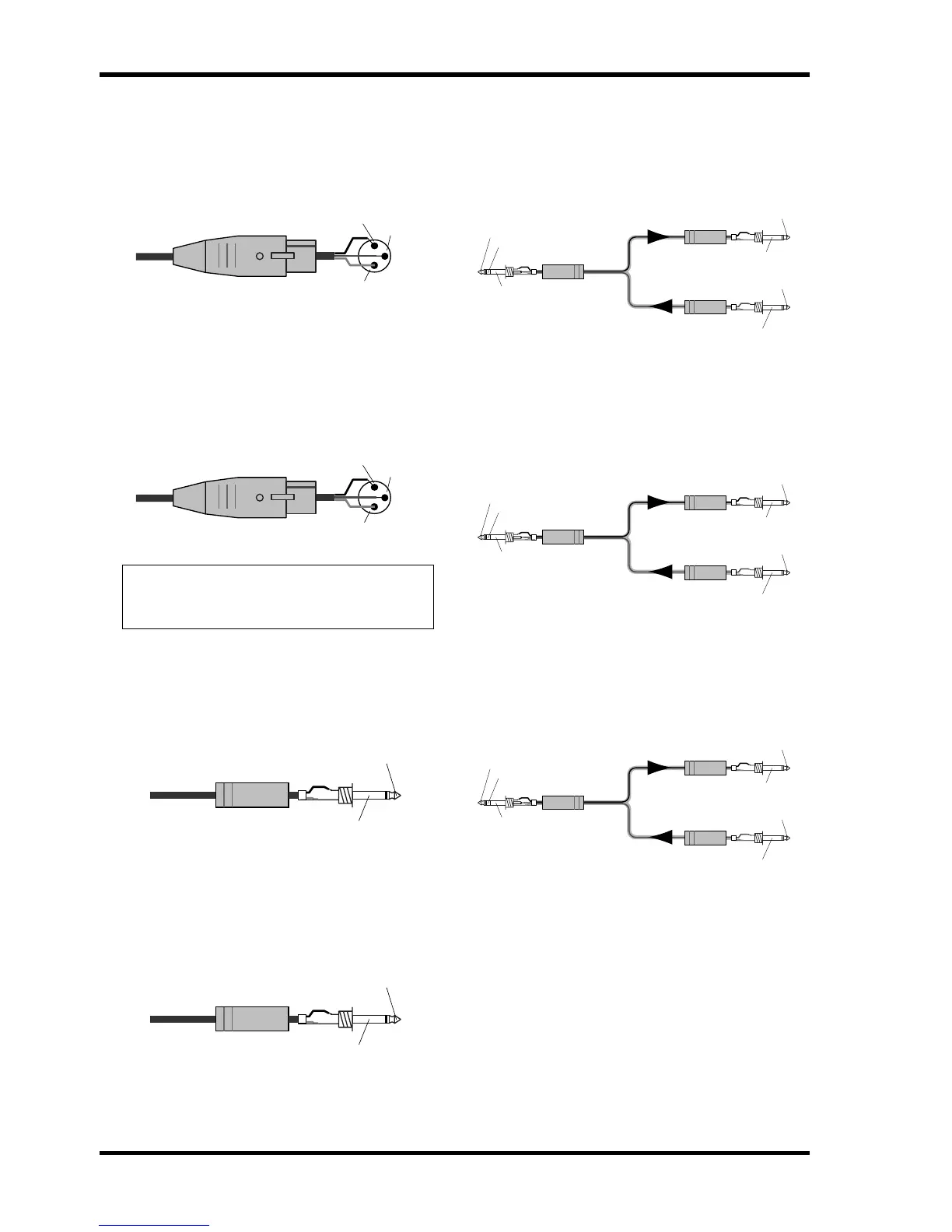
These are XLR-3-32 output jacks (balanced) that out-
put the signal of the stereo/monaural master section.
Nominal output level of each jack is +4 dB. The pin
wiring is as follows.
F
MONITOR OUT
jacks
These are XLR-3-32 output jacks (balanced) that out-
put the signal of the stereo/monaural master section,
or the monitor source that is selected by the control
panel. Nominal output level of each jack is +4 dB.
The pin wiring is as follows.
G
SUB IN MATRIX
jacks
These are 1/4" phone jacks (unbalanced) for mixing a
line level signal from an external device into the
MATRIX bus. Nominal input level is +4 dB. The pin
wiring is as follows.
H
SUB IN ST L
/
R
,
MONO/C
jack
These are 1/4" phone jacks (unbalanced) for mixing a
line level signal from an external device into the STE-
REO bus L/R and MONO/C bus respectively. Nomi-
nal input level is +4 dB. The pin wiring is as follows.
I
INSERT I/O
G1/A7
–
G8/A14
jacks
These are TRS phone jacks for inserting an external
effect processor into each output channel of the G1/
A7–G8/A14 section. Nominal input level is 0 dB. The
pin wiring is as follows.
J
INSERT I/O AUX
jacks
These are TRS phone jacks for inserting an external
effect processor into each output channel of the AUX
1–6 section. Nominal input level is 0 dB. The pin wir-
ing is as follows.
K
INSERT I/O ST L
/
R
,
MONO
jacks
These are TRS phone jacks for inserting an external
effect processor into each output channel of the ste-
reo/monaural master section. Nominal input level is
0 dB. The pin wiring is as follows.
Note:
When outputting the monitor source
selected by the control panel, only the MONITOR
OUT L/R jacks are used.
Female XLR plug
1 (ground)
3 (cold)
2 (hot)
Female XLR plug
1 (ground)
3 (cold)
2 (hot)
1/4" phone plug
Tip (send)
Sleeve (ground)
1/4" phone plug
Tip (send)
Sleeve (ground)
1/4" phone plug
1/4" phone plug
1/4" TRS phone plug
To processor’s input
From processor’s output
Connect to INSERT I/O jack
Tip (send)
Tip (send)
Ring (return)
Sleeve (ground)
Sleeve (ground)
Tip (return)
Sleeve (ground)
1/4" phone plug
1/4" phone plug
1/4" TRS phone plug
To processor’s input
From processor’s output
Connect to INSERT I/O jack
Tip (send)
Tip (send)
Ring (return)
Sleeve (ground)
Sleeve (ground)
Tip (return)
Sleeve (ground)
1/4" phone plug
1/4" phone plug
1/4" TRS phone plug
To processor’s input
From processor’s output
Connect to INSERT I/O jack
Tip (send)
Tip (send)
Ring (return)
Sleeve (ground)
Sleeve (ground)
Tip (return)
Sleeve (ground)


 To Next Page