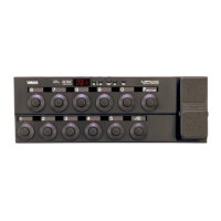
UB99
15
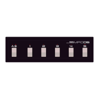
3-1-8. SW&LED Check
Push [+] SW. The following display appears.
Then, LED (+) will be turned on.
3-1-9. SW&LED Check
Push [STORE] SW. The following display appears.
Then, three LEDs, LED (-), LED [ON/OFF], and LED
(+) will be turned on.
Check for the OK sign in the display.
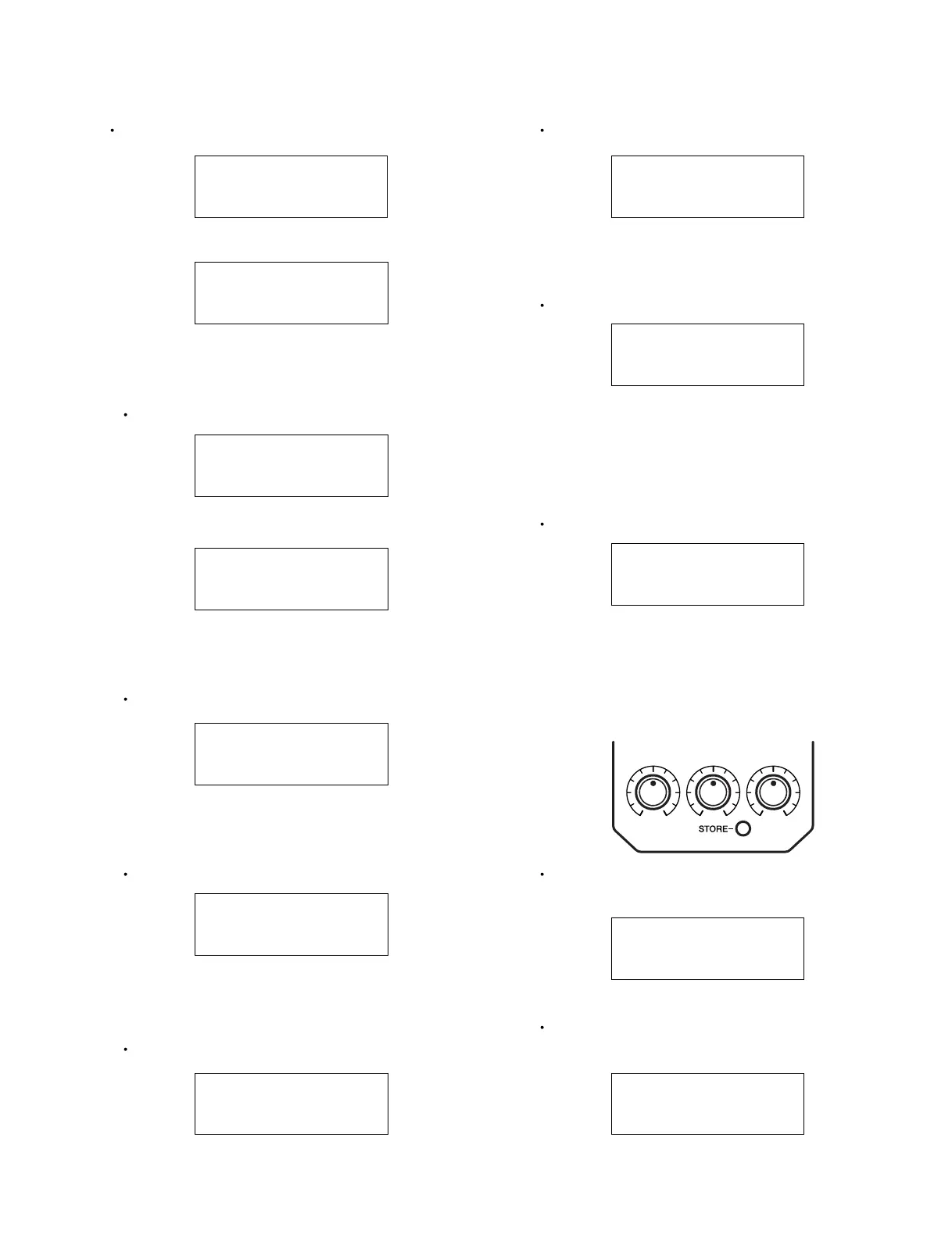
3-1-10. VR Check
Push [ON/OFF] SW. The following display appears.
The LEDs will be turned off.
"**" represents each of VR values, and "[]" shows the
position of the VR to be inspected.
3-1-11. VR Check
Turn VR1 (Control 1) fully clockwise. The following
display appears.
3-1-12. VR Check
Turn VR1 (Control 1) fully counterclockwise. The
following display appears.
3-1-3. SRAM Check
Push [ON/OFF] SW. The following display appears.
In a short time, the display is changed as follows.
Check for the OK sign in the display.
3-1-4. FLASH ROM Check
Push [ON/OFF] SW. The following display appears.
In a short time, the display is changed as follows.
Check for the OK sign in the display.
3-1-5. SW&LED Check
Push [ON/OFF] SW. The following display appears.
Check for the OK sign in the display.
3-1-6. SW&LED Check
Push [
-
] SW. The following display appears.
and LED (-) will be turned on.
3-1-7. SW&LED Check
Push [ON/OFF] SW. The following display appears.
Then, LED [ON/OFF] will be turned on.
UB99 SRAM CHECK
N OW WRITE & READ
UB99 SRAM CHECK
OK PUSH [ONOFF] SW
UB99 FLASH ROM
NOW WRITE & READ
UB99 FLASH ROM
OK PUSH [ONOFF] SW
UB99 SW&LED CHECK
PUSH [
-
] SWITCH
UB99 SW&LED CHECK
PUSH [ON/OFF] SW
UB99 SW&LED CHECK
PUSH [+] SWITCH
UB99 SW&LED CHECK
PUSH [STORE] SW
UB99 SW&LED CHECK
OK PUSH [ONOFF] SW
UB99 VOL1 CHECK
MAX [**] ** **
UB99 VOL1 CHECK
MIN [ ff ] ** **
UB99 VOL1 CHECK
UP [00] ** **
VR1 VR2 VR3