16
UB99
3-1-19. VR Check
Turn VR3 (Control 3) slightly clockwise. The following
display appears.
Check for the OK sign in the display.
3-1-20. USB Check
Push [ON/OFF] SW. The following display appears.
3-1-21. USB Check
Connect with PC by USB cable. The following display
appears.
3-1-22. USB Check
Remove the USB cable. The following display appears.
Check for the OK sign in the display.
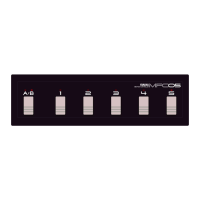
3-1-23. LCD Check
Push [ON/OFF] SW. The following display appears.
3-1-24. LCD Check
Push [ON/OFF] SW. The following display appears.
All the LEDs will be turned on.
3-1-13. VR Check
Turn VR1 (Control 1) slightly clockwise. The following
display appears.
3-1-14. VR Check
Turn VR2 (Control 2) fully clockwise. The following
display appears.
3-1-15. VR Check
Turn VR2 (Control 2) fully counterclockwise. The
following display appears.
3-1-16. VR Check
Turn VR2 (Control 2) slightly clockwise. The following
display appears.
3-1-17. VR Check
Turn VR3 (Control 3) fully clockwise. The following
display appears.
3-1-18. VR Check
Turn VR3 (Control 3) fully counterclockwise. The
following display appears.
UB99 VOL2 CHECK
MAX ** [**] **
UB99 VOL2 CHECK
MIN ** [ff ] **
UB99 VOL2 CHECK
UP ** [00] **
UB99 VOL3 CHECK
MAX ** ** [**]
UB99 VOL3 CHECK
MIN ** ** [ff]
UB99 VOL3 CHECK
UP ** ** [00]
UB99 VOL3 CHECK
OK PUSH [ONOFF] SW
UB99 USB CHECK
V10103 CNECT USB
UB99 USB CHECK
DISCONNECT CABLE
UB99 USB CHECK
OK PUSH [ONOFF] SW
UB99 LCD CHECK
PUSH [ON/OFF] SW
■■■■■■■■■■■■
■■■■■■■■■■■■