6
UB99
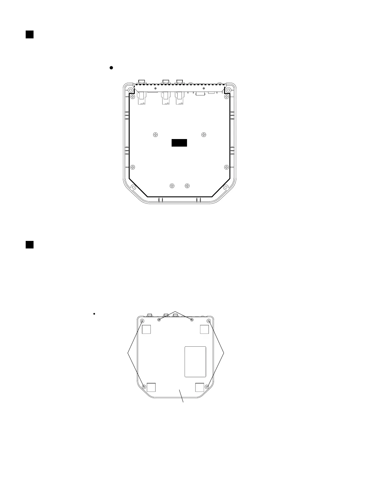
CIRCUIT BOARD LAYOUT
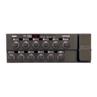
DISASSEMBLY PROCEDURE
1. Bottom Case
(Time required: About 1 minute)
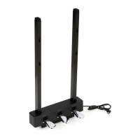
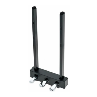
1-1. Remove the four (4) screws marked [40] and the
two (2) screws marked [30]. The bottom case can
then be removed. (Fig.1)
1. ボトムケース(所要時間:約 1 分)
1-1. [40]のネジ4本と[30]のネジ2本を外し、ボトムケー
スを外します。(図 1)
[40] [40]
[30]
Bottom case(ボトムケース)
[30]: Bind Head Tapping Screw-B 3.0X8 MFZN2BL (EP600190)
[40]: Bind Head Tapping Screw-P 4.0X8 MFZN2BL (VB931600)
Fig.1
DM
Bottom view
Bottom view
(ユニットレイアウト)
(分解手順)
(+バインドBタイト)
(+バインドPタイト)
(図1)