EasyManua.ls Logo

Yamaha MC2410M - Front Panel Operations; Input Section.2

Yamaha MC2410M
58 pages
Print Icon
To Next Page IconTo Next Page
To Previous Page IconTo Previous Page
Loading...
FRONT
PANEL
OPERATION
CH.
INPUT
SECTION
-£
-IB
tlB
|
.~L°&
_I
,
o'
lo
o'
lo
I_#u&j
_Atua
J
r~""i
|l
o'
lo
f57E1fi575
,_-=-P*H._
I
r
“
“—i
ocd
ocd
i
i
0
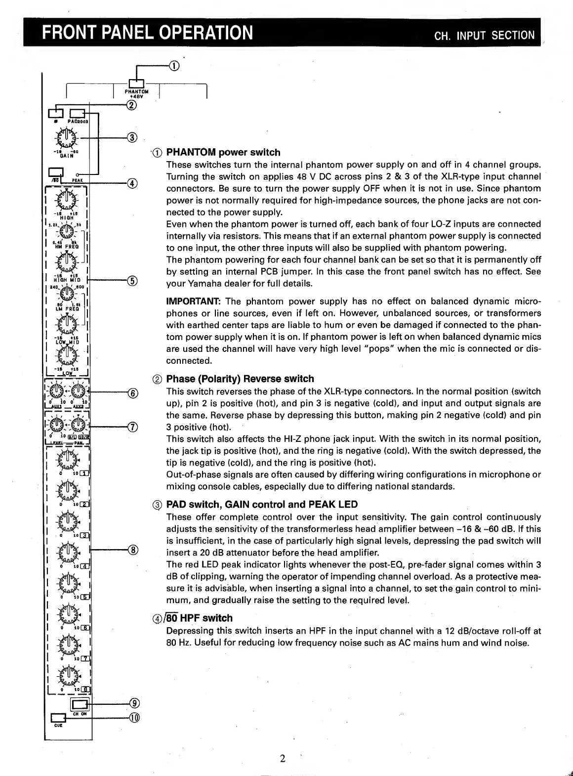
PHANTOM
power
switch
These
switches
turn
the
internal
phantom
power
supply
on
and
off
in
4
channel
groups.
Turning
the
switch
on
applies
48
V
DC
across
pins
2
&
3
of
the
XLR-type
input
channel
connectors.
Be
sure
to
turn
the
power
supply
OFF
when
it
is
not
in
use.
Since
phantom
power
is
not
normally
required
for
high-impedance
sources,
the
phone
jacks
are
not
con¬
nected
to
the
power
supply.
Even
when
the
phantom
power
is
turned
off,
each
bank
of
four
LO-Z
inputs
are
connected
internally
via
resistors.
This
means
that
if
an
external
phantom
power
supply
is
connected
to
one
input,
the
other
three
inputs
will
also
be
supplied
with
phantom
powering.
The
phantom
powering
for
each
four
channel
bank
can
be
set
so
that
it
is
permanently
off
by
setting
an
internal
PCB
jumper.
In
this
case
the
front
panel
switch
has
no
effect.
See
your
Yamaha
dealer
for
full
details.
IMPORTANT:
The
phantom
power
supply
has
no
effect
on
balanced
dynamic
micro¬
phones
or
line
sources,
even
if
left
on.
However,
unbalanced
sources,
or
transformers
with
earthed
center
taps
are
liable
to
hum
or
even
be
damaged
if
connected
to
the
phan¬
tom
power
supply
when
it
is
on.
If
phantom
power
is
left
on
when
balanced
dynamic
mics
are
used
the
channel
will
have
very
high
level
"pops"
when
the
mic
is
connected
or
dis¬
connected.
0
Phase
(Polarity)
Reverse
switch
This
switch
reverses
the
phase
of
the
XLR-type
connectors.
In
the
normal
position
{switch
up),
pin
2
is
positive
(hot),
and
pin
3
is
negative
(cold),
and
input
and
output
signals
are
the
same.
Reverse
phase
by
depressing
this
button,
making
pin
2
negative
(cold)
and
pin
3
positive
(hot).
This
switch
also
affects
the
Hl-Z
phone
jack
input.
With
the
switch
in
its
normal
position,
the
jack
tip
is
positive
(hot),
and
the
ring
is
negative
(cold).
With
the
switch
depressed,
the
tip
is
negative
(cold),
and
the
ring
is
positive
(hot).
Out-of-phase
signals
are
often
caused
by
differing
wiring
configurations
in
microphone
or
mixing
console
cables,
especially
due
to
differing
national
standards.
(|)
PAD
switch,
GAIN
control
and
PEAK
LED
These
offer
complete
control
over
the
input
sensitivity.
The
gain
control
continuously
adjusts
the
sensitivity
of
the
transformerless
head
amplifier
between
-16
&
-60
dB.
If
this
is
insufficient,
in
the
case
of
particularly
high
signal
levels,
depressing
the
pad
switch
will
insert
a
20
dB
attenuator
before
the
head
amplifier.
The
red
LED
peak
indicator
lights
whenever
the
post-EQ,
pre-fader
signal
comes
within
3
dB
of
clipping,
warning
the
operator
of
impending
channel
overload.
As
a
protective
mea¬
sure
it
is
advisable,
when
inserting
a
signal
into
a
channel,
to
set
the
gain
control
to
mini¬
mum,
and
gradually
raise
the
setting
to
the
required
level.
®/80
HPF
switch
Depressing
this
switch
inserts
an
HPF
in
the
input
channel
with
a
12
dB/octave
roll-off
at
80
Hz.
Useful
for
reducing
low
frequency
noise
such
as
AC
mains
hum
and
wind
noise.
Q-
2