Do you have a question about the Yamaha MSR250 and is the answer not in the manual?
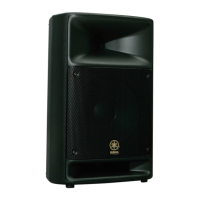
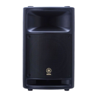
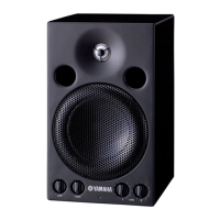
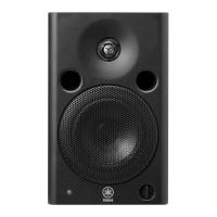
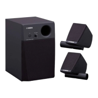
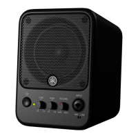
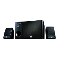
General physical and electrical characteristics of the speaker unit.
Specifications related to the amplifier unit, including output power and sensitivity.
Procedure for removing the front grille assembly of the speaker.
Steps for disassembling and removing the LF (woofer) speaker unit.
Procedure to separate the front and rear cabinet units for access.
Steps for disassembling and removing the HF (tweeter) speaker unit.
Procedure for removing the NETWORK circuit board assembly.
Steps for disassembling and removing the amplifier assembly.
Procedure for removing the MOTHER circuit board.
Procedure for removing the INPUT circuit board.
Procedure for removing the CONTROL circuit board.
Procedure for removing the AMP circuit board.
Procedure for removing the POWER-b circuit board.
Procedure for removing the cooling fan unit.
Procedure for removing the power transformer and POWER-a circuit board.
Procedure for removing the power switch and AC inlet.
Component layout diagram for the AMP circuit board.
Component layout diagram for the CONTROL circuit board.
Component layout diagram for the INPUT circuit board.
Component layout diagram for the NETWORK circuit board.
Component layout diagram for the MOTHER circuit board.
Component layout diagram for the POWER-a circuit board.
Component layout diagram for the POWER-b circuit board.
Specifies the test conditions required for inspections.
Specifies the ambient temperature and humidity for inspections.
Block and level signal flow diagram of the MSR250.
Detailed circuit diagram for the INPUT section of the MSR250.
Detailed circuit diagram for the CONTROL section of the MSR250.
Detailed circuit diagram for MOTHER and NETWORK sections.
Detailed circuit diagram for the AMP section of the MSR250.
Detailed circuit diagram for the POWER supply sections.
| Tweeter | Yes |
|---|---|
| Speaker type | 2-way |
| Number of drivers | 1 |
| Speaker placement | Floor |
| Audio output channels | 1.0 channels |
| Woofer diameter (imperial) | 10 \ |
| Subwoofer driver diameter (imperial) | 1 \ |
| Product color | Black |
| LED indicators | Power |
| Housing material | Polypropylene (PP) |
| Recommended usage | Speaker set unit |
| Impedance | 4 Ω |
| Frequency range | 55 - 20000 Hz |
| RMS rated power | 250 W |
| Crossover frequency | 4000 Hz |
| Total Harmonic Distortion (THD) | 1 % |
| Microphone sensitivity | -50 dB |
| Connectivity technology | Wired |
| Power consumption (typical) | 40 W |
| Depth | 298 mm |
|---|---|
| Width | 342 mm |
| Height | 544.5 mm |
| Weight | 14100 g |