EasyManua.ls Logo

Yamaha MSP Series User Manual

Yamaha MSP Series
20 pages
To Next Page IconTo Next Page
Page #1 background imageLoading...
Page #1 background image
SERVICE MANUAL
SPECIFICATIONS (総合仕様)..................................................................... 3
DIMENSIONS (寸法図).............................................................................. 4
PANEL LAYOUT (パネルレイアウト)......................................................... 5
CIRCUIT BOARD LAYOUT (ユニットレイアウト.................................... 6
DISASSEMBLY PROCEDURES (分解手順)............................................... 7
CIRCUIT BOARDS (シート基板図)........................................................... 11
INSPECTIONS (検査)............................................................................... 13
BLOCK DIAGRAM (ブロックダイアグラム)............................................ 15
CIRCUIT DIAGRAM (回路図)................................................................... 16
PARTS LIST
CONTENTS (目次)
PA 011843
Copyright (c) Yamaha Corporation. All rights reserved. 06.11
HAMAMATSU, JAPAN
このサービスマニュアルはエコパルプ
(ECF:無塩素系漂白パルプ)を使用しています。
200612-34650
Question and Answer IconNeed help?

Do you have a question about the Yamaha MSP Series and is the answer not in the manual?

Yamaha MSP Series Specifications

General IconGeneral
BrandYamaha
ModelMSP Series
CategorySpeakers
LanguageEnglish

Summary

Product Specifications

General Specifications Overview

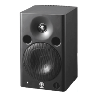
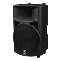
Details on speaker type, frequency response, output level, dimensions, weight, and enclosure.

Speaker Components Specifications

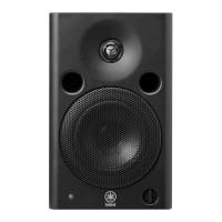
Specifications for LF and HF speaker components, including cone size and shielding.

Amplifier and Power Specifications

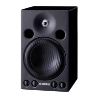
Specifications for output power, input sensitivity, controls, indicators, and power consumption.

Speaker Dimensions and Diagram

Physical Dimensions Diagram

Diagram illustrating the physical dimensions (W x H x D) of the speaker unit.

Panel Layout and Controls

Front Panel Controls and Indicators

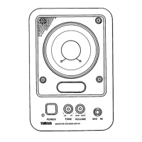
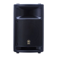
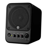
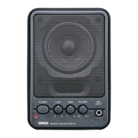
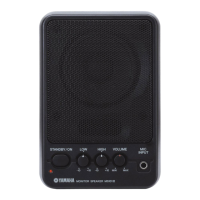
Identification and layout of controls and indicators on the front panel.

Rear Panel Connectors and Controls

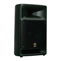
Identification and layout of connectors and controls on the rear panel.

Internal Circuit Board Layout

Component Placement Diagram

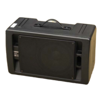
Diagram showing the placement of major internal components like drivers, transformer, and amplifier.

Disassembly and Component Removal

Woofer Removal Procedure

Step-by-step guide for removing the woofer component.

Rear Panel Assembly Removal

Instructions for removing the rear panel assembly.

Tweeter Removal Procedure

Instructions for removing the tweeter component.

Power Transformer Removal

Steps to remove the power transformer from the unit.

AMP Circuit Board Removal

Procedures for removing the AMP circuit board.

Input Circuit Board Removal

Procedures for removing the INPUT circuit board.

Volume Circuit Board Removal

Steps for removing the VOLUME circuit board.

LED Circuit Board Removal

Steps for removing the LED circuit board.

Heat Sink Removal

Instructions for removing the heat sink.

Power Switch Removal

Instructions for removing the power switch.

Circuit Board Diagrams

AMP Circuit Board Schematic

Detailed schematic and component layout for the amplifier circuit board.

INPUT Circuit Board Schematic

Detailed schematic and component layout for the input circuit board.

Volume Circuit Board Diagram

Diagram showing the volume control circuit board layout.

LED Circuit Board Diagram

Diagram showing the LED indicator circuit board layout.

Inspection and Testing

General Inspection Settings

Settings for voltage measurement, load, level VR, and tone-control switches.

Electric Performance Tests

Tests for output power, gain, frequency response, tone control, noise, and DC voltage.

Muting and Protection Circuit Tests

Procedures for testing muting operation and protection circuit functionality.

Clipping and Stability Tests

Tests for clipping level indication and circuit stability under varying conditions.

Factory Settings Verification

Verification of default factory settings for power, trim, and level controls.

Block Diagram of Signal Flow

Audio Signal Path Diagram

Diagram illustrating the signal path from input to output, including key functional blocks.

Complete Circuit Diagram

Overall Electronic Circuit Schematic

Detailed schematic showing the interconnections of all electronic components and circuits.

Parts List and Inventory

Overall Assembly Parts List

List of all parts for the overall assembly, including part numbers and descriptions.

Electrical Components List

List of electrical components, including circuit boards, fuses, and connectors.

Related product manuals