EasyManua.ls Logo

Yamaha MS400 Service Manual

Yamaha MS400
31 pages
To Next Page IconTo Next Page
Page #1 background imageLoading...
Page #1 background image
MS400
1
SERVICE MANUAL
PA
011556
20001210-98000
1.415K-215 K Printed in Japan 2000.12
HAMAMATSU, JAPAN
This document is printed on chlorine free (ECF) paper with soy ink.
POWERED SPEAKER
CONTENTS
SPECIFICATIONS ................................................... 3
DIMENSIONS ........................................................... 4
BLOCK DIAGRAM
............................ 4
PANEL LAYOUT .................................... 5
CIRCUIT BOARD LAYOUT ................. 6
WIRING ..................................................................... 7
DISASSEMBLY PROCEDURE .............................. 8
IC BLOCK DIAGRAM ................................... 10
CIRCUIT BOARDS ........................................ 11
INSPECTIONS ............................................................ 16
OVERALL CIRCUIT DIAGRAM ........................... 19
PARTS LIST
MS400
w
w
w
.
x
i
a
o
y
u
1
6
3
.
c
o
m
Q
Q
3
7
6
3
1
5
1
5
0
9
9
2
8
9
4
2
9
8
T
E
L
1
3
9
4
2
2
9
6
5
1
3
9
9
2
8
9
4
2
9
8
0
5
1
5
1
3
6
7
3
Q
Q
TEL 13942296513 QQ 376315150 892498299
http://www.xiaoyu163.com

Other manuals for Yamaha MS400

Question and Answer IconNeed help?

Do you have a question about the Yamaha MS400 and is the answer not in the manual?

Yamaha MS400 Specifications

General IconGeneral
BrandYamaha
ModelMS400
CategorySpeakers
LanguageEnglish

Summary

SPECIFICATIONS

General Specifications

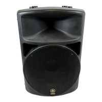
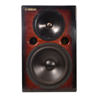
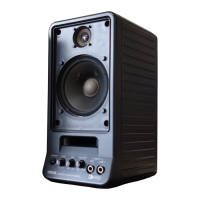
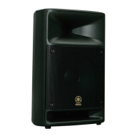
Details the speaker's type, units, frequency range, output level, dimensions, and weight.

Amplifier Specifications

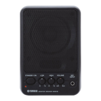
Lists output power, crossover frequency, input sensitivity, impedance, and power requirements.

DIMENSIONS

BLOCK DIAGRAM

PANEL LAYOUT

Rear Panel Layout

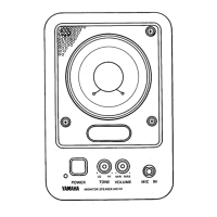
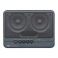
Shows the location and labeling of all rear panel connectors and controls.

CIRCUIT BOARD LAYOUT

WIRING

DISASSEMBLY PROCEDURE

Cabinet and Speaker Disassembly

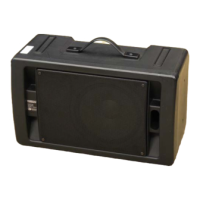
Step-by-step guide for removing amplifier, cabinet, baffle, and speaker components.

AMP CIRCUIT BOARDS

AMP Circuit Board Identification

Lists part numbers for various amplifier circuit boards (1/5 to 5/5).

Power Transformer Removal

Details the removal procedure for the power transformer unit.

IC BLOCK DIAGRAM

Handle and Heat Sink Removal

CIRCUIT BOARD DETAILS

AMP1/5 Circuit Board Overview

Detailed component layout and schematic for the AMP1/5 circuit board.

AMP1/5 Circuit Board - Component Side

AMP1/5 Circuit Board - Pattern Side

AMP2/5 Circuit Board Layout

AMP3/5 Circuit Board Layout

AMP4/5 Circuit Board Layout

AMP5/5 Circuit Board Layout

IN2/2 Circuit Board Layout

INSPECTIONS

Amplifier Unit Preparation and Inspection

Covers preparation, power, adjustment, midpoint potential, gain, and distortion checks for the amplifier.

Inspection Details and Tests

Finished Product Inspection

OVERALL CIRCUIT DIAGRAM 1/2

OVERALL CIRCUIT DIAGRAM 2/2

PARTS LIST

Destination Abbreviations

Lists abbreviations used for different country/region model destinations.

Parts List Notations

Explains warnings and notations used within the parts list section.

OVERALL ASSEMBLY

Cabinet Assembly Parts

Accessories List

AMPLIFIRE ASSEMBLY

Amplifier Circuit Board Identification

ELECTRICAL PARTS

Electrical Components - Group 1

Lists electrical components like capacitors, connectors, and diodes with their specifications.

Electrical Components - Group 2

Electrical Components - Group 3

Electrical Components - Group 4

Electrical Components - Group 5

Electrical Components - Group 6

Related product manuals