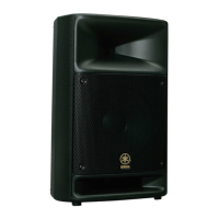
MS400
8
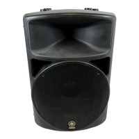
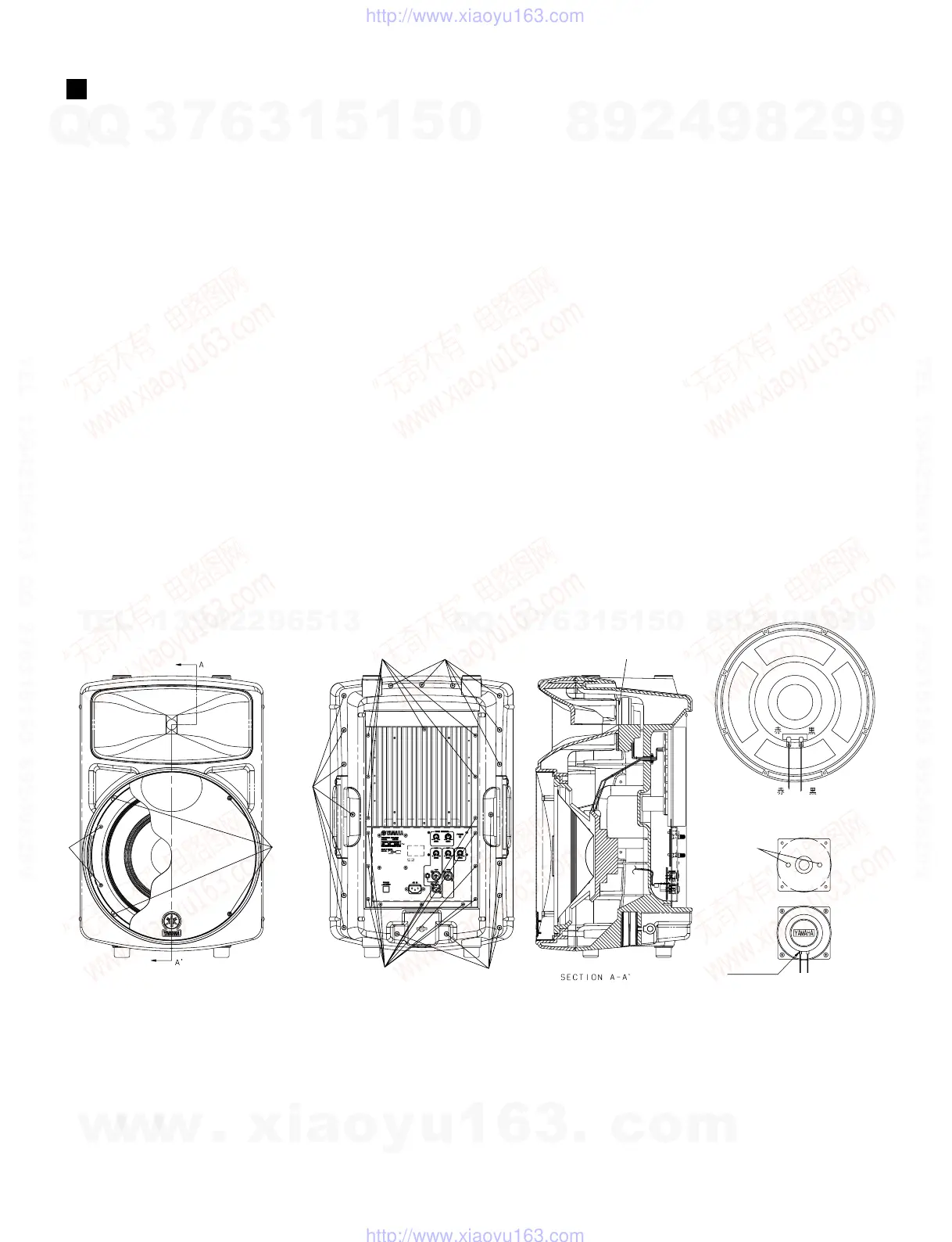
DISASSEMBLY PROCEDURE
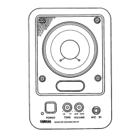
Fig.1
1. Amplifier assembly
1-1. Remove the sixteen (16) screws marked [180A]. The
amplifier assembly can then be removed. (Fig. 1)
2. Cabinet assembly and buffle assembly
2-1. Remove the nineteen (19) screws marked [170]. The
buffle assembly can then be removed from the
capinet assembly. (Fig. 1)
3. Speakers (38cm, 25mm)
3-1. Remove the buffle assembly from the cabinet
assembly. (See Procedure 2.)
3-2. To remove the 38cm speaker, remove the four (4)
screws marked [180B] and the front grille. (Fig. 1)
3-3. Remove the eight (8) bolts marked [70]. The 38cm
speaker can then be removed. (Fig. 1)
3-4. To remove the 25mm speaker, remove the four (4)
screws marked [120]. Then remove the speaker with
the bracket. (Fig. 1)
3-5. Remove the two (2) screws marked [100]. The 25mm
speaker can then be removed from the bracket. (Fig. 1)
[70]: Hexagonal Bolt 5.0 X 35 MFZN2BL (V6389200)
[120]: Bind Head Tapping Screw-P 5.0 X 30 MFZN2BL (V6405200)
[170]: Bind Head Tapping Screw-P 5.0 X 50 MFZN2BL (V6084800)
[180]: Bind Head Screw-Giza 4 X 16 MFZN2BL (V6396400)
[170]
[180B]
[170]
[180A]
[180A]
[70]
[170]
38cm Speaker
[100]
Red Black
Red Black
25mm Speaker
Red marking
Yellow
Blue
[120]
w
w
w
.
x
i
a
o
y
u
1
6
3
.
c
o
m
Q
Q
3
7
6
3
1
5
1
5
0
9
9
2
8
9
4
2
9
8
T
E
L
1
3
9
4
2
2
9
6
5
1
3
9
9
2
8
9
4
2
9
8
0
5
1
5
1
3
6
7
3
Q
Q
TEL 13942296513 QQ 376315150 892498299
TEL 13942296513 QQ 376315150 892498299
http://www.xiaoyu163.com
http://www.xiaoyu163.com
 Loading...