MS400
9
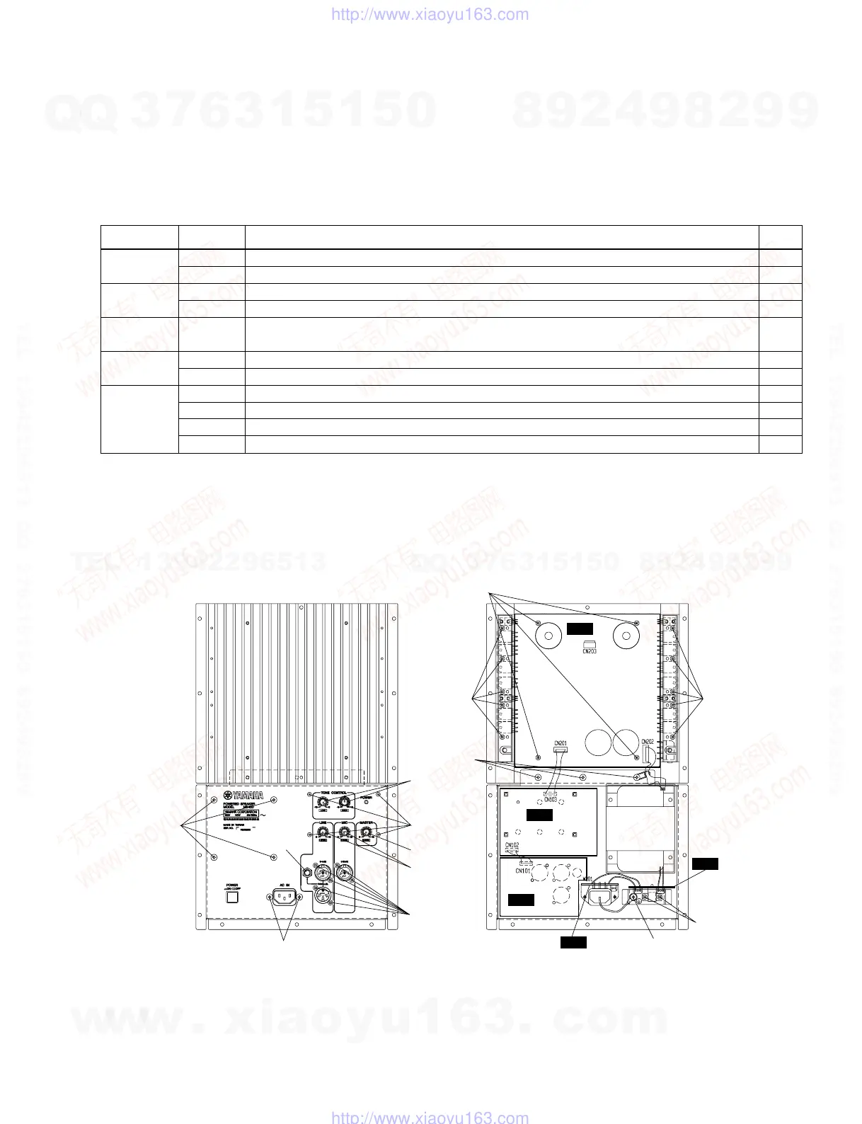
Fig.2
4. AMP Circuit Boards (1/5 to 5/5)
4-1. Remove the amplifier assembly. (See Procedure 1.)
4-2. Remove the screws and the knob from each circuit
board, which can then be removed. (Fig. 2)
5. Power transformer
5-1. Remove the amplifier assembly. (See Procedure 1.)
5-2. Remove the four (4) screws marked [80B]. The power
transformer can then be removed. (Fig. 2)
[80]: Bonding Screw-B 4.0 X 12 MFZN2BL (V7242900)
AMP1/5 90 Bind Head Tapping Screw-B 3.0 X 12 MFZN2BL (VQ074600) 10
Circuit Board
100 Bind Head Screw SP 3.0 X 8 MFZN2Y (EG330290) 4
AMP2/5 80A Bonding Screw-B 4.0 X 12 MFZN2BL (V7242900) 2
Circuit Board
130 Bind Head Screw 4.0 X 8 MFZN2BL (VP156800) 1
AMP3/5
110A Bonding Screw-B 3.0 X 8 MFZN2BL (VN413300) 2
Circuit Board
AMP4/5 110B Bonding Screw-B 3.0 X 8 MFZN2BL (VN413300) 6
Circuit Board
Hexagonal Nut 1
AMP5/5 150 Knob MX-GREEN/D-GRAY (VU860200) 2
Circuit Board
160 Knob ORANGE/D-GRAY (VV625800) 2
170 Knob RED/D-GRAY (VU860400) 1
200 Button 3 X 25 MFZN2BL (V3289800) 4
PCB Name Ref No. Description Q'ty
[80B]
Hexagonal
nut
[80A]
[150]
[160]
[200]
[170]
[110B]
[100]
1/5
[90] [90]
5/5
4/5
[120]
2/5
3/5
[110A]
[130]
AMP
AMP
AMP
AMP
AMP
w
w
w
.
x
i
a
o
y
u
1
6
3
.
c
o
m
Q
Q
3
7
6
3
1
5
1
5
0
9
9
2
8
9
4
2
9
8
T
E
L
1
3
9
4
2
2
9
6
5
1
3
9
9
2
8
9
4
2
9
8
0
5
1
5
1
3
6
7
3
Q
Q
TEL 13942296513 QQ 376315150 892498299
TEL 13942296513 QQ 376315150 892498299
http://www.xiaoyu163.com
http://www.xiaoyu163.com
 Loading...