EasyManua.ls Logo

Yamaha MU100 Service Manual

Yamaha MU100
38 pages
To Next Page IconTo Next Page
Page #1 background imageLoading...
Page #1 background image
SERVICE MANUAL
TONE GENERATOR
CONTENTS
SPECIFICATIONS
···································································································
3
PANEL LAYOUT
·······································································································
4
CIRCUIT BOARD LAYOUT
···············································································
5
BLOCK DIAGRAM
···································································································
6
DISASSEMBLY PROCEDURE
·······································································
7
LSI PIN DESCRIPTION
····················································································
12
IC BLOCK DIAGRAM
·························································································
14
CIRCUIT BOARDS
·······························································································
16
TEST PROGRAM
··································································································
18
MIDI / COMPUTER CONNECTING CABLES
····································
23
ERROR MESSAGES
··························································································
24
INITIALIZE
·················································································································
25
MIDI IMPLEMENTATION CHART
······························································
26
OVERALL CIRCUIT DIAGRAM
···································································
27
PARTS LIST
SY
011450
PLG-100DX PLG-100VL PLG-100VH
HAMAMATSU, JAPAN
0.32K-3942 Printed in Japan '99.01

Other manuals for Yamaha MU100

Question and Answer IconNeed help?

Do you have a question about the Yamaha MU100 and is the answer not in the manual?

Yamaha MU100 Specifications

General IconGeneral
BrandYamaha
ModelMU100
CategoryRecording Equipment
LanguageEnglish

Summary

Important Safety and Handling Information

Service Safety and Handling Precautions

Crucial safety warnings for servicing, lithium battery handling, and chemical content notices.

Specifications

Panel Layout Overview

Front Panel Layout

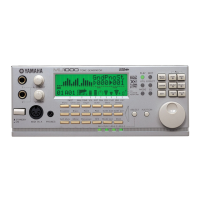
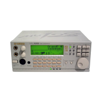
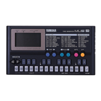
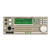
Diagram and labels identifying controls and indicators on the MU100's front panel.

Rear Panel Layout

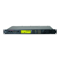
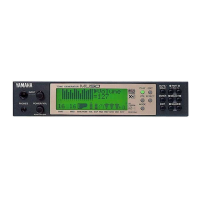
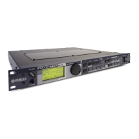
Diagram and labels identifying connectors and switches on the MU100's rear panel.

Circuit Board Layout

Block Diagram

Disassembly Procedure

Bottom Assembly Removal

Steps for removing the bottom assembly, including screw details.

DM Circuit Board Removal

Procedure to remove the DM circuit board using specific screws.

PSW, PVR Boards, and LCD Removal

Steps to remove PSW, PVR circuit boards, and the LCD panel.

Installing a Plug-in Board

Installation Instructions and Precautions

Detailed steps and safety precautions for installing or removing plug-in boards.

LSI Pin Description

HD6432655A00F CPU LSI Pinout

Comprehensive pinout description for the main CPU LSI, detailing name, I/O, and function.

IC Block Diagrams

Logic Gate and Multiplexer IC Block Diagrams

Block diagrams for Hex Inverter, Bus Buffer, Demultiplexer, D-Type Flip Flop, Multiplexer ICs.

Transceiver IC Block Diagram

Block diagram for the Octal 3-State Bus Transceiver IC.

Circuit Boards Overview

DM Circuit Board Layout

Visual layout of the DM circuit board, showing component placement and connectors.

PSW and PVR Circuit Board Layouts

Visual layouts of the PSW and PVR circuit boards, showing component placement and connectors.

Test Program Guide

Test Program Preparations and Entry

Required instruments, how to enter the test program, and basic navigation.

Test Procedure and Error Handling

Guide for proceeding through tests, selecting tests, and handling detected errors.

MIDI and Computer Connecting Cables

Standard MIDI Cable

Specifications and diagram for a standard MIDI connection cable.

Computer Connection Cables (Mac/PC)

Specifications and diagrams for connecting MU100 to Mac and PC computers via MIDI.

Error Messages

Initialize Functions

Initialization Operation and Types

Steps to access and perform initialization for GM, C/M, Performance, and Drum modes.

MIDI Implementation Chart

MU100 Overall Circuit Diagram

Parts List

Overall Assembly Parts List

Exploded view of the MU100 unit showing major assembly components.

Front, Top, and Bottom Assembly Parts List

Detailed parts breakdown for front, top, and bottom panel assemblies.

Electrical Components List

Comprehensive list of electrical parts like capacitors, resistors, and ICs.

Related product manuals