EasyManua.ls Logo

Yamaha MX200-12 User Manual

Yamaha MX200-12
57 pages
To Next Page IconTo Next Page
Page #1 background imageLoading...
Page #1 background image
MIXING CONSOLE
TABLE DE MIXAGE
MISCHPULTE
CONSOLA DE MEZCLA
Operation Manual
Manuel d’instructions
Bedienungsanleitung
Manual de Operación
B
A
20dB
PEAK
–16
–60
GAIN
80
–15 +15
HIGH
–15
+15
MID
–15
+15
LOW
010
AUX 1
0
10
AUX 2
0
10
AUX 3
0
10
AUX 4
LR
PAN
PFL
P
O
S
T
P
R
E
10
5
0
5
10
15
20
30
40
00
12345678
–10dB
RR
LL
1R
1L/MONO
2R
2L/MONO
3
1
4
2
LR
+4B
–10dB
TAPE IN REC OUT
STEREO OUT +4dB
AUX RETURN +4dB
AUX SEND +4dB
MONO OUT
010
PHONES
–15
+15
HIGH
–15
+15
LOW
0
10
AUX 1
0
10
LEVEL
0
10
REC OUT
0
10
TAPE IN
AUX RETURN 1 AUX RETURN 2
L ST R
PHONESMONO
ON
AFL
AFLAFLAFL AFL
AUX SEND 4AUX SEND 3AUX SEND 2AUX SEND 1
METER SELECT
L ST R
1 AUX 2
MONO PFL/AFL
3 AUX 4
+6
+4
+2
0
–2
–4
–7
–10
–15
–20
–00
+6
+4
+2
0
–2
–4
–7
–10
–15
–20
–00
–15
+15
HIGH
–15
+15
LOW
0
10
AUX 1
0
10
LEVEL
10
5
0
5
10
15
20
30
00
10
5
0
5
10
15
20
30
00
10
5
0
5
10
15
20
30
00
10
5
0
5
10
15
20
30
00
10
5
0
5
10
15
20
30
40
00
10
5
0
5
10
15
20
30
40
00
10
5
0
5
10
15
20
30
40
00
10
5
0
5
10
15
20
30
40
00
B
A
20dB
PEAK
–16
–60
GAIN
80
–15 +15
HIGH
–15
+15
MID
–15
+15
LOW
010
AUX 1
0
10
AUX 2
0
10
AUX 3
0
10
AUX 4
LR
PAN
PFL
P
O
S
T
P
R
E
10
5
0
5
10
15
20
30
40
00
B
A
20dB
PEAK
–16
–60
GAIN
80
–15 +15
HIGH
–15
+15
MID
–15
+15
LOW
010
AUX 1
0
10
AUX 2
0
10
AUX 3
0
10
AUX 4
LR
PAN
PFL
P
O
S
T
P
R
E
10
5
0
5
10
15
20
30
40
00
B
A
20dB
PEAK
–16
–60
GAIN
80
–15 +15
HIGH
–15
+15
MID
–15
+15
LOW
010
AUX 1
0
10
AUX 2
0
10
AUX 3
0
10
AUX 4
LR
PAN
PFL
P
O
S
T
P
R
E
10
5
0
5
10
15
20
30
40
00
B
A
20dB
PEAK
–16
–60
GAIN
80
–15 +15
HIGH
–15
+15
MID
–15
+15
LOW
010
AUX 1
0
10
AUX 2
0
10
AUX 3
0
10
AUX 4
LR
PAN
PFL
P
O
S
T
P
R
E
10
5
0
5
10
15
20
30
40
00
B
A
20dB
PEAK
–16
–60
GAIN
80
–15 +15
HIGH
–15
+15
MID
–15
+15
LOW
010
AUX 1
0
10
AUX 2
0
10
AUX 3
0
10
AUX 4
LR
PAN
PFL
P
O
S
T
P
R
E
10
5
0
5
10
15
20
30
40
00
B
A
20dB
PEAK
–16
–60
GAIN
80
–15 +15
HIGH
–15
+15
MID
–15
+15
LOW
010
AUX 1
0
10
AUX 2
0
10
AUX 3
0
10
AUX 4
LR
PAN
PFL
P
O
S
T
P
R
E
ON
10
5
0
5
10
15
20
30
40
00
B
A
20dB
PEAK
–16
–60
GAIN
80
–15 +15
HIGH
–15
+15
MID
–15
+15
LOW
010
AUX 1
0
10
AUX 2
0
10
AUX 3
0
10
AUX 4
LR
PAN
PFL
P
O
S
T
P
R
E
ONONONONONONONON
MIXING CONSOLE
PHANTOM
PFL
INPUT A
INPUT B
OUT IN
INPUT CH INSERT I/O 0dB
OUT IN
123456789
123456789
123456789
10 11 12 13 14 15 16 17 18 19 20 21 22 23 24
10 11 12 13 14 15 16 17 18 19 20 21 22 23 24
10 11 12 13 14 15 16 17 18 19 20 21 22 23 24
B
A
20dB
PEAK
–16
–60
GAIN
80
–15 +15
HIGH
–15
+15
MID
–15
+15
LOW
010
AUX 1
0
10
AUX 2
0
10
AUX 3
0
10
AUX 4
LR
PAN
PFL
P
O
S
T
P
R
E
10
5
0
5
10
15
20
30
40
00
10
5
0
5
10
15
20
30
40
00
B
A
20dB
PEAK
–16
–60
GAIN
80
–15 +15
HIGH
–15
+15
MID
–15
+15
LOW
010
AUX 1
0
10
AUX 2
0
10
AUX 3
0
10
AUX 4
LR
PAN
PFL
P
O
S
T
P
R
E
10
5
0
5
10
15
20
30
40
00
B
A
20dB
PEAK
–16
–60
GAIN
80
–15 +15
HIGH
–15
+15
MID
–15
+15
LOW
010
AUX 1
0
10
AUX 2
0
10
AUX 3
0
10
AUX 4
LR
PAN
PFL
P
O
S
T
P
R
E
10
5
0
5
10
15
20
30
40
00
B
A
20dB
PEAK
–16
–60
GAIN
80
–15 +15
HIGH
–15
+15
MID
–15
+15
LOW
010
AUX 1
0
10
AUX 2
0
10
AUX 3
0
10
AUX 4
LR
PAN
PFL
P
O
S
T
P
R
E
10
5
0
5
10
15
20
30
40
00
B
A
20dB
PEAK
–16
–60
GAIN
80
–15 +15
HIGH
–15
+15
MID
–15
+15
LOW
010
AUX 1
0
10
AUX 2
0
10
AUX 3
0
10
AUX 4
LR
PAN
PFL
P
O
S
T
P
R
E
10
5
0
5
10
15
20
30
40
00
B
A
20dB
PEAK
–16
–60
GAIN
80
–15 +15
HIGH
–15
+15
MID
–15
+15
LOW
010
AUX 1
0
10
AUX 2
0
10
AUX 3
0
10
AUX 4
LR
PAN
PFL
P
O
S
T
P
R
E
10
5
0
5
10
15
20
30
40
00
B
A
20dB
PEAK
–16
–60
GAIN
80
–15 +15
HIGH
–15
+15
MID
–15
+15
LOW
010
AUX 1
0
10
AUX 2
0
10
AUX 3
0
10
AUX 4
LR
PAN
PFL
P
O
S
T
P
R
E
10
5
0
5
10
15
20
30
40
00
B
A
20dB
PEAK
–16
–60
GAIN
80
–15 +15
HIGH
–15
+15
MID
–15
+15
LOW
010
AUX 1
0
10
AUX 2
0
10
AUX 3
0
10
AUX 4
LR
PAN
PFL
P
O
S
T
P
R
E
B
A
20dB
PEAK
–16
–60
GAIN
80
–15 +15
HIGH
–15
+15
MID
–15
+15
LOW
010
AUX 1
0
10
AUX 2
0
10
AUX 3
0
10
AUX 4
LR
PAN
PFL
P
O
S
T
P
R
E
10
5
0
5
10
15
20
30
40
00
10
5
0
5
10
15
20
30
40
00
B
A
20dB
PEAK
–16
–60
GAIN
80
–15 +15
HIGH
–15
+15
MID
–15
+15
LOW
010
AUX 1
0
10
AUX 2
0
10
AUX 3
0
10
AUX 4
LR
PAN
PFL
P
O
S
T
P
R
E
10
5
0
5
10
15
20
30
40
00
B
A
20dB
PEAK
–16
–60
GAIN
80
–15 +15
HIGH
–15
+15
MID
–15
+15
LOW
010
AUX 1
0
10
AUX 2
0
10
AUX 3
0
10
AUX 4
LR
PAN
PFL
P
O
S
T
P
R
E
10
5
0
5
10
15
20
30
40
00
B
A
20dB
PEAK
–16
–60
GAIN
80
–15 +15
HIGH
–15
+15
MID
–15
+15
LOW
010
AUX 1
0
10
AUX 2
0
10
AUX 3
0
10
AUX 4
LR
PAN
PFL
P
O
S
T
P
R
E
10
5
0
5
10
15
20
30
40
00
B
A
20dB
PEAK
–16
–60
GAIN
80
–15 +15
HIGH
–15
+15
MID
–15
+15
LOW
010
AUX 1
0
10
AUX 2
0
10
AUX 3
0
10
AUX 4
LR
PAN
PFL
P
O
S
T
P
R
E
10
5
0
5
10
15
20
30
40
00
B
A
20dB
PEAK
–16
–60
GAIN
80
–15 +15
HIGH
–15
+15
MID
–15
+15
LOW
010
AUX 1
0
10
AUX 2
0
10
AUX 3
0
10
AUX 4
LR
PAN
PFL
P
O
S
T
P
R
E
10
5
0
5
10
15
20
30
40
00
B
A
20dB
PEAK
–16
–60
GAIN
80
–15 +15
HIGH
–15
+15
MID
–15
+15
LOW
010
AUX 1
0
10
AUX 2
0
10
AUX 3
0
10
AUX 4
LR
PAN
PFL
P
O
S
T
P
R
E
10
5
0
5
10
15
20
30
40
00
B
A
20dB
PEAK
–16
–60
GAIN
80
–15 +15
HIGH
–15
+15
MID
–15
+15
LOW
010
AUX 1
0
10
AUX 2
0
10
AUX 3
0
10
AUX 4
LR
PAN
PFL
P
O
S
T
P
R
E
Question and Answer IconNeed help?

Do you have a question about the Yamaha MX200-12 and is the answer not in the manual?

Yamaha MX200-12 Specifications

General IconGeneral
Channels12
Inputs12
EQ Bands3-band
Aux Sends2
Phantom PowerYes
TypeAnalog
Inputs - Mic Preamps4

Summary

Introduction

Product Features

Input Channel Capabilities

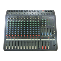
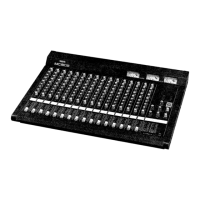
Provides 8-24 input channels mixed down to a stereo signal, with various connection options.

Monitoring Functions

Includes PFL (Pre Fader Listen) and AFL (After Fader Listen) for flexible audio monitoring.

Connectivity Options

Features XLR and phone inputs, INSERT I/O, AUX SEND/RETURN, and TAPE IN/REC OUT.

Power and EQ Features

Includes phantom power for microphones and a 3-band equalizer on each channel.

Safety Precautions

Environmental and Handling Precautions

Avoid excessive heat, humidity, dust, vibration, and physical shocks. Handle with care.

Maintenance and Repair

Do not open the case; refer all maintenance to qualified Yamaha service personnel.

Connection and Power Safety

Always power off before connections, handle cables carefully, and use the correct power supply.

Cleaning Instructions

Clean the unit with a soft, dry cloth only. Never use solvents.

UK Mains Wiring Notice

Important notice for the UK regarding mains lead colour coding for plug connections.

Control Panel: Channel Section

Input Selector

Selects the input connector (INPUT A XLR or INPUT B phone jack) for the channel.

PAD Switch

Provides 20dB of level reduction for high input signals.

GAIN Control

Adjusts input signal level to an appropriate range for optimal S/N and dynamic range.

PEAK Indicator

Lights red at 3dB before clipping to warn of potential signal distortion.

80Hz High-Pass Filter

Switch to cut signals below 80Hz at 12dB/octave for low-frequency noise reduction.

Equalizer Section

Provides ±15dB control over High (12kHz), Mid (2.5kHz), and Low (80Hz) frequencies.

AUX1-4 Controls

Adjusts signal levels sent to AUX buses; AUX1/2 are pre-fader, AUX3/4 are post-fader.

PAN Control

Assigns channel signal to STEREO L/R bus, determining stereo position.

Channel ON Switch

Enables/disables signal output to STEREO L/R and AUX buses for the channel.

PFL Switch

Monitors the pre-fader channel input signal through headphones.

Channel Fader

Controls the output level of the input channel signal for volume balance.

Control Panel: Master Section

STEREO ON Switch

Turns the ST OUT output on/off; affects ST meters but not MONO OUT.

STEREO L, R Master Faders

Adjust final level of combined signals and send to STEREO OUT connectors.

MONO ON Switch

Turns the MONO OUT on/off.

MONO AFL Switch

Monitors the MONO OUT signal through headphones.

MONO Fader

Adjusts the output level of the MONO OUT connector.

AUX SEND 1-4 AFL Switches

Monitor output signals sent to AUX SEND 1-4 via PFL/AFL meter.

AUX SEND Faders

Adjust the level of output signals sent from AUX SEND 1-4.

AUX RETURN 1, 2 Controls

Control level of signals from effect units to L/R bus and AUX SENDs, with LOW EQ.

REC OUT Control

Adjusts output level of REC OUT jacks for tape deck connection.

TAPE IN Control

Adjusts monitor volume for tape deck connected to TAPE IN jacks.

PHONES Control

Adjusts the volume for headphones connected to the PHONES jack.

PHONES Jack

Connect headphones here to monitor various signals.

Meter Section and Select Switch

Selects signals displayed on dual-function LED meters for level monitoring.

Phantom Indicator

Indicates when the PHANTOM switch is turned on.

PFL Indicator

Lights when any channel PFL switch is on, showing level on PFL/AFL meter.

Connectors

INPUT A (XLR)

XLR type connectors for microphones (50-600Ω) or line level devices.

INPUT B (Phone)

Balanced phone connectors for microphones or line level devices.

INPUT CH INSERT I/O

Jacks between head amp and EQ for inserting external processors.

TAPE IN Connector

Connect DAT or cassette deck for monitoring.

REC OUT Connector

Connect DAT or cassette deck to record audio from STEREO OUT.

STEREO OUT (L, R)

Stereo output for power amps driving main speakers or for recording.

MONO OUT Connector

Mono output for sub amp, live performance recording, or phase checks.

Rear Panel Connections

POWER Switch

Turns the mixer's power on or off.

PHANTOM Switch

Turns phantom power (+48V) on or off for all channels.

AUX SEND (1-4) Jacks

Unbalanced jacks for outputting signals to external effect units or monitors.

AUX RETURN Jacks

Unbalanced jacks to receive audio from effect units or for supplementary inputs.

Application Example

Specifications: General

Output Level and Distortion

Details maximum output levels for STEREO, MONO, and AUX SEND, and total harmonic distortion.

Frequency Response and Noise

Specifies frequency response range and hum/noise levels for various outputs.

Voltage Gain and Crosstalk

Lists maximum voltage gains and crosstalk figures at 1kHz.

Input Gain and EQ Specifications

Details gain control range, pad function, and equalizer frequency/range.

Meters, Indicators, and Phantom Power

Information on LED meters, peak indicators, and phantom power specifications.

Power Supply Requirements

Specifies voltage, frequency, and power consumption for different models and regions.

Specifications: Input

Channel Input Details

Details PAD, Gain, input impedance, sensitivity, and connector type for CH Input.

Auxiliary Return and Insert Specs

Input specifications for AUX RETURN and INSERT IN connectors.

Tape Input Specifications

Details input level, impedance, and connector type for TAPE IN.

Specifications: Output

Main Output Specifications

Details output level, impedance, and connector type for STEREO OUT and MONO OUT.

Auxiliary Send and Insert Output Specs

Output specifications for AUX SEND and INSERT OUT connectors.

Headphone Output Specs

Details output level, impedance, and connector type for PHONES OUT.
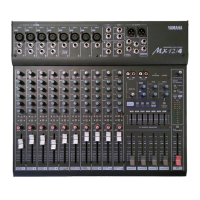
Block and Level Diagrams

Dimensions

Related product manuals