910 11 126 7 8
23 4 5 6 7 8 1 1 3 4 5 2
61L 61H
10-3 Rubber Contact
10-3-1 Remove the white and black keys corresponding to
the rubber contacts to be removed.
(See Fig. 6, Fig. 7 and Procedure 10-2.)
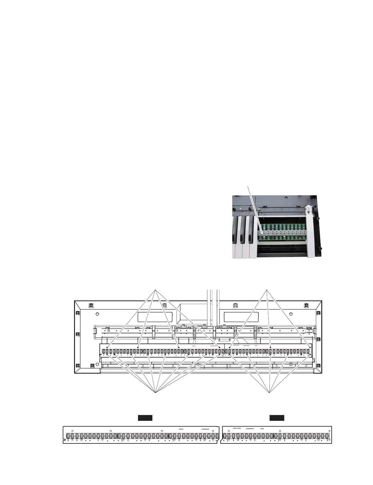
10-3-2 Remove the rubber contacts. (Fig. 7, Photo 4)
10-4 61L Circuit Board
10-4-1 Remove the white and black keys from C1 to B3.
(See Fig. 6 and Procedure 10-2.)
10-4-2 Remove the four (4) screws marked [100A] and eight
(8) screws marked [100B]. The 61L circuit board can
then be removed. (Fig. 7)
* When installing the 61L circuit board, tighten the
screws in numerical order from 1 to 12. (Fig. 8)
10-5 61H Circuit Board
10-5-1 Remove the white and black keys from C4 to C6. (See
Fig. 6 and Procedure 10-2.)
10-5-2 Remove the three (3) screws marked [100B] and five
(5) screws marked [100C]. The 61H circuit board can
then be removed. (Fig. 7)
* When installing the 61H circuit board, tighten
the screws in numerical order from 1 to 8. (Fig. 8)
10-3 接点ゴム
10-3-1外そうとしている接点ゴムに対応した白鍵・黒鍵を
外します。(図 6、図 7、10-2 項参照)
10-3-2それぞれの接点ゴムを外します。(図 7、写真 4)
10-4 シート 61L
10-4-1C1 〜 B3 の白鍵・黒鍵を外します。(図 6、10-2 項参照)
10-4-2[100A]のネジ 4 本と[110B]のネジ 8 本を外して、
シート 61L を外します。(図 7)
※ シート 61L を取り付けるときは、番号 1 〜 12 の
順にネジを締めてください。(図 8)
10-5 シート 61H
10-5-1C4 〜 C6 の白鍵・黒鍵を外します。(図 6、10-2 項参照)
10-5-2[100B]のネジ 3 本と[110C]のネジ 5 本を外して、
シート 61H を外します。(図 7)
※ シート 61H を取り付けるときは、番号1〜8の
順にネジを締めてください。(図 8)
Photo. 4
(写真 4)
Fig. 7
(図 7)
Fig. 8
(図 8)
Rubber contact
(接点ゴム)
[100A]
[110B]
[100B]
[110C]
<Top view (上面図)>
13
MX61/MX49