Do you have a question about the Yamaha PC2002 and is the answer not in the manual?
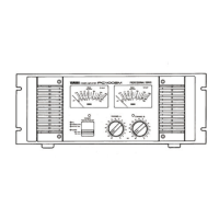
Describes the PC2002M amplifier's system orientation and the manual's purpose and content.
Recommends reading the entire manual, highlighting brief instructions for experienced users.
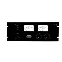
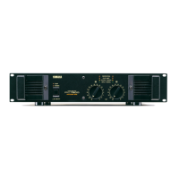
Clarifies that the PC2002 is identical to PC2002M except for the absence of Peak Reading Meters.
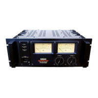
Explains the PC2002M's peak reading meters, their accuracy, and advantage in showing headroom.
Details the detented, dB-calibrated input attenuators and their benefits for setup and tracking.
Describes the flexible input connector options: XLR (balanced) and phone jacks (unbalanced).
Explains how to adapt the amplifier for monaural operation using the rear-panel MODE switch.
Identifies and explains the function of the Power switch, Thermal/Protection indicators, Peak meters, and Clip indicators.
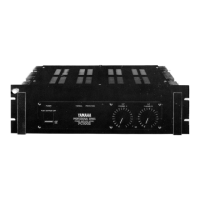
Details speaker output terminals, ground switch, XLR and phone jack inputs, and mode/balance switches.
Details continuous power output, frequency response, and power bandwidth specifications.
Lists Total Harmonic Distortion, Intermodulation Distortion, and S/N Ratio.
Covers input sensitivity, impedance, damping factor, slew rate, and channel separation.
Includes relay muting time, indicators, front/rear panel controls, power requirements, dimensions, and weight.
Graph showing output power characteristics relative to load impedance.
Illustrates the amplifier's power band width across frequencies.
Graphs detailing frequency response under various modes and load conditions.
Graphs showing Total Harmonic Distortion (THD) relative to output power for stereo and mono modes.
Graphs showing input and output impedance characteristics against frequency.
Oscilloscope traces demonstrating accurate response at 20 Hz, 1 kHz, and 20 kHz.
Shows Total Harmonic Distortion for a 20 kHz sine wave signal at high output.
Oscilloscope traces illustrating slew rate (stereo/mono) and rise time measurements.
Explains peak vs. average power, FTC standards, and the importance of high power for transients.
Discusses Harmonic Distortion, THD, clipping distortion, and crossover distortion.
Explains IM distortion and its low, inaudible level in the PC2002M.
Details frequency response, stability, and the benefit of limited sub-audio response.
Explains power bandwidth and its importance for reproducing high-energy musical material.
Discusses channel separation and the amplifier's low hum and noise levels.
Explains slew rate, input impedance, and input sensitivity requirements.
Details protection circuits, thermal specifications, and the concept of gain.
Explains the extremely low output impedance and the function of the damping factor.
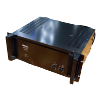
Covers shelf mounting and permanent rack mounting, emphasizing ventilation.
Provides guidelines for mounting in road cases, including bracing and fan considerations.
Details dimensions and design for front and rear fan panels and securing braces for rack mounting.
Presents the block diagram illustrating signal flow, power supply, and indicator circuits.
Provides detailed dimensional drawings in millimeters and inches for the amplifier.
Lists the weight of the PC2002 and PC2002M models in pounds and kilograms.
Provides specific instructions for connecting the mains lead wires according to UK color codes.
Informs users about Yamaha's worldwide service network and qualified dealer support.
| Total Harmonic Distortion | 0.005% |
|---|---|
| Input Sensitivity | 1.23V |
| Type | Stereo Power Amplifier |
| Input Impedance | 20kΩ |
| Frequency Response | 10Hz to 50kHz |
| Damping Factor | 200 |
| Signal to Noise Ratio | 110dB |