EasyManua.ls Logo

Yamaha PC4002 User Manual

Yamaha PC4002
43 pages
To Next Page IconTo Next Page
Page #1 background imageLoading...
Page #1 background image
PROFESSIONAL
SERIES
POWER
AMPLIFIERS
PC4002/4002M
OPERATING
MANUAL
MODE
D’EMPLOI
BEDIENUNGSANLEITUNG
I
un
И
|
|
ҮАМАНА
Question and Answer IconNeed help?

Do you have a question about the Yamaha PC4002 and is the answer not in the manual?

Yamaha PC4002 Specifications

General IconGeneral
BrandYamaha
ModelPC4002
CategoryAmplifier
LanguageEnglish

Summary

About This Manual

Important Notice For The United Kingdom

Connecting the Plug and Cord

Instructions for connecting the mains lead to the plug in the UK.

Precautions

Introduction

Front Panel

Power Switch/Power Indicator (RED)

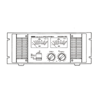
Controls power ON/OFF and indicates power supply status.

Protection Indicator (RED)

Indicates muting during power-up or protection circuit activation.

Thermal Fan Indicator (RED)

Indicates high-speed fan operation due to high temperature.

BTL Indicator (GREEN)

Indicates when BTL (mono bridging) mode is selected.

Peak Meters (PC 4002M ONLY)

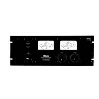
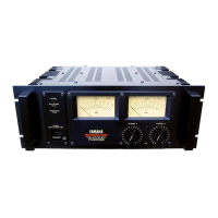
Displays peak output levels on PC4002M models.

Signal Indicators (GREEN) (PC4002 ONLY)

Indicates input signal presence on PC4002 models.

Clip Indicators

Lights up when output distortion reaches approximately 1%.

Input Attenuators

Controls input signal attenuation in 1dB increments.

Knob Locks

Prevents accidental resetting of attenuator levels.

Rear Panel

Speaker Terminals (For Each Channel)

Connects speaker systems to the amplifier output terminals.

Ground Lift Switch (For Each Channel)

Isolates ground to prevent hum from ground loops.

Input Connectors (XLR-3-31)

Female XLR connectors for input signals.

Input Connectors (XLR-3-32)

Male XLR connectors for signal pass-through.

Phone Input Connectors

1/4-inch TRS connectors for balanced/unbalanced input.

Mode Selector Switch (BTL)

Selects bridged (mono) operation mode.

Instructions for Connection of Speaker Cables

General Specifications

Performance Graphs

Mounting

Shelf Mounting

Instructions for placing the unit on a flat surface.

Portable Rack Mounting

Guidelines for mounting in portable rack cases.

Permanent-Installation Rack Mounting

Procedures for mounting in standard 19-inch equipment racks.

Installation Precautions

Cleaning the Fan Filter Elements

Block Diagram

Dimensions

Service

Related product manuals