EasyManua.ls Logo

Yamaha PM3500 - 2.2 PM3500 rear panel features; 2.2.1 Standard (monaural) input module

Yamaha PM3500
57 pages
Print Icon
To Next Page IconTo Next Page
To Previous Page IconTo Previous Page
Loading...
Channel
inputs,
sub
inputs,
sub
outputs
and
primary
outputs
use
XLR-3
type
connectors,
wired
as
follows:
ы
[шы]
оно
|
ao
[m
Note
the
male
and
female
polarities
of
these
connectors
on
the
PM3500;
male
connectors
are
generally
used
as
outputs,
and
female
as
inputs.
This
can
assist
you
in
remembering
the
direction
of
signal
flow.
INSERT
IN/OUT
points
are
1/4"
tip-ring-sleeve
con-
nectors,
wired
as
follows:
[Pim
__|
Connection
е
mm
|
Tip
—
(cold)
Input
channel
XLR-type
connectors
are
electronically
balanced,
but
optional
input
isolation
transformers
can
be
installed
on
a
per-module
basis.
All
output
XLRs
are
also
electronically
balanced.
If
required,
optional
isolation
transformers
can
be
sup-
plied
in
a
19-inch
rack-mount
unit,
each
unit
accommo-
dating
eight
transformers.
In
this
way,
inputs
and
outputs
can
be
provided
with
extra
grounding
isola-
tion
and
common
mode
rejection
where
required,
without
the
price
in
direct
costs,
weight
or
signal
qual-
ity
where
the
transformers
are
not
required.
2—Features
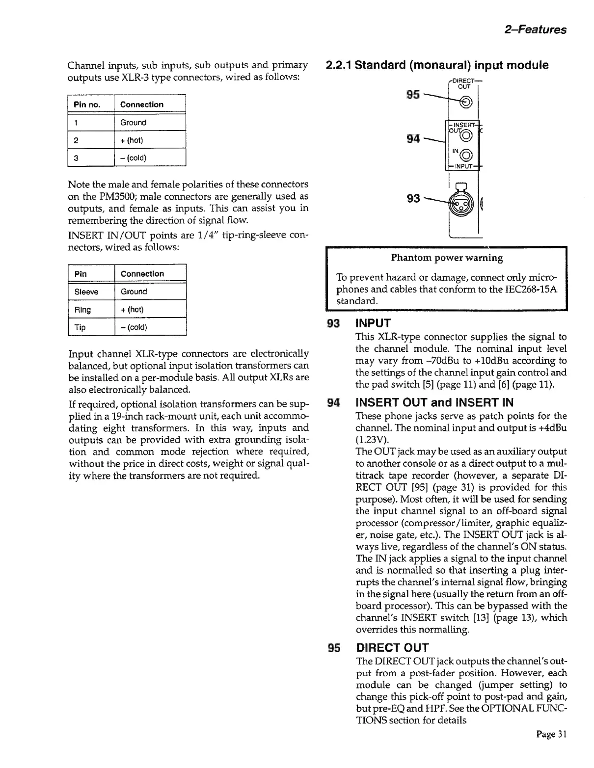
2.2.1
Standard
(monaural)
input
module
95
94
Phantom
power
warning
To
prevent
hazard
or
damage,
connect
only
micro-
phones
and
cables
that
conform
to
the
IEC268-15A
standard.
93
94
95
INPUT
This
XLR-type
connector
supplies
the
signal
to
the
channel
module.
The
nominal
input
level
may
vary
from
-70dBu
to
+10dBu
according
to
the
settings
of
the
channel
input
gain
control
and
the
pad
switch
[5]
(page
11)
and
[6]
(page
11).
INSERT
OUT
and
INSERT
IN
These
phone
jacks
serve
as
patch
points
for
the
channel.
The
nominal
input
and
output
is
+4dBu
(1.23V).
The
OUT
jack
may
be
used
as
an
auxiliary
output
to
another
console
or as
a
direct
output
to
a
mul-
titrack
tape
recorder
(however,
a
separate
DI-
RECT
OUT
[95]
(page
31)
is
provided
for
this
purpose).
Most
often,
it
will
be
used
for
sending
the
input
channel
signal
to
an
off-board
signal
processor
(compressor/limiter,
graphic
equaliz-
er,
noise
gate,
etc.).
The
INSERT
OUT
jack
is
al-
ways
live,
regardless
of
the
channel’s
ON
status.
The
IN
jack
applies
a
signal
to
the
input
channel
and
is
normalled
so
that
inserting
a
plug
inter-
rupts
the
channel’s
internal
signal
flow,
bringing
in
the
signal
here
(usually
the
return
from
an
off-
board
processor).
This
can
be
bypassed
with
the
channel’s
INSERT
switch
[13]
(page
13),
which
overrides
this
normalling.
DIRECT
OUT
The
DIRECT
OUT
jack
outputs
the
channel’s
out-
put
from
a
post-fader
position.
However,
each
module
can
be
changed
(jumper
setting)
to
change
this
pick-off
point
to
post-pad
and
gain,
but
pre-EQ
and
HPF.
See
the
OPTIONAL
FUNC-
TIONS
section
for
details
Page
31