EasyManua.ls Logo

Yamaha SPX990 Service Manual

Yamaha SPX990
53 pages
To Next Page IconTo Next Page
Page #1 background imageLoading...
Page #1 background image
^CONTENTS
(g'^)
SPECIFICATI0NS(J^B-f±^5^)
2/3
PANEL
LAY0UT(/';4'
;uu<
7'0
h
)
4
CIRCUIT BOARD LAYOUK
zl
-
y h
U
Y
r ^
I-
)
6
BLOCK
DiAGRAiVl(7'D
8
DIIViENSIONS(-t>=fell])
9
DISASSEMBLY
PROCEDURE(:j^m^)iS)
10
LSI
PIN
DESCRIPTIONCLSIJSiT^ia^HMa)
14
1C
BLOCK
DIAGRAMCICVP
19
CIRCUIT
BOARDS('>-
^
»[U)
20
TEST
PROGRAM
(
7^^
i-
-7^
v
A)
26/30
CHECKS &
ADJUSTMENTS(^^^tllH^li)
34/35
RAM
INITIALIZE(RAMYA'>i^^YX)
36
ERROR
MESSAGES(x
5-7
y-tz--7) 36
MIDI DATA
F0RMAT<MID!^--
7
7=1--
V y
h
)
37/42
MIDI
IMPLEMENTATION
CHART
47
PRESET PROGRAM LIST
48
OPERATION MAP
50
PARTS LIST
SPX990

Other manuals for Yamaha SPX990

Question and Answer IconNeed help?

Do you have a question about the Yamaha SPX990 and is the answer not in the manual?

Yamaha SPX990 Specifications

General IconGeneral
Sampling Frequency44.1 kHz
Dynamic Range90dB
TypeDigital Multi-Effect Processor
Total Harmonic Distortion0.03%
Input ConnectorsXLR, 1/4" TRS
Output ConnectorsXLR, 1/4" TRS
MIDIIn, Out, Thru
Power SupplyAC 120V, 60Hz
EffectsReverb, Delay, Modulation, Pitch Change
Dimensions480 x 44 x 280 mm
Weight3.5 kg
Frequency Response20Hz - 20kHz (+1dB, -3dB)

Summary

Important Notices and Safety Warnings

General Safety Warnings

Provides critical safety instructions and warnings for servicing the product to prevent injury or damage.

Chemical Content Notice

Alerts users about potential chemical hazards in components and safe handling procedures.

Specifications Overview

Electrical & Audio Characteristics

Details on frequency response, dynamic range, distortion, input/output levels, and impedance.

Panel Layout and Identification

Front Panel Controls and Indicators

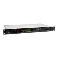
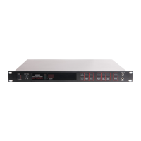
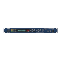
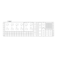
Identifies and describes the functions of front panel buttons, knobs, and displays.

Rear Panel Connectors and Switches

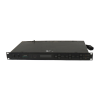
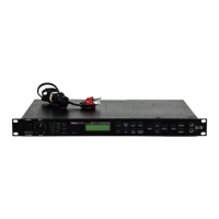
Details the rear panel's input/output jacks, MIDI terminals, and switches.

System Block Diagram

Overall System Block Diagram

Shows the functional blocks and signal flow of the SPX990 processor.

Disassembly Procedures

Top Cover and Front Panel Removal

Step-by-step instructions for removing the top cover and front panel assembly.

LSI Pin Descriptions

Integrated Circuit Block Diagrams

Test Program Procedures

Test Program Overview and Preparation

Covers test setup, initiation, navigation, and overall program flow.

Checks and Adjustments

Preparation and Basic Performance Checks

Covers unit preparation and checks for gain, frequency response, distortion, output, and noise.

Adjustment Procedures

Detailed steps for adjusting clipping levels and audio gain settings.

Error Messages Guide

Interpreting Error Codes

Lists error codes (E1-E4) and their corresponding meanings for troubleshooting.

MIDI Data Format Specifications

MIDI Implementation Chart

MIDI Protocol Compatibility

Details transmitted and recognized MIDI messages and system modes.

Related product manuals