Do you have a question about the Yamaha SPX50D and is the answer not in the manual?
Details of the unit's electrical performance parameters including frequency response, dynamic range, and THD.
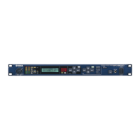
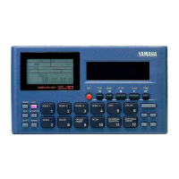
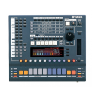
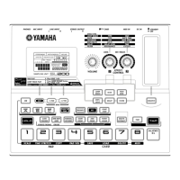
Description of controls and indicators on the front of the unit, such as keys, display, and input level controls.
Description of connectors and controls on the rear of the unit, including input, output, and MIDI ports.
Specification of MIDI input and output connectors and their functions.
General specifications including dimensions, weight, and power consumption.
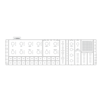
Labeled diagram of the front panel controls and displays, with corresponding numbers.
Labeled diagram of the rear panel connectors, with corresponding numbers.
Pinout and function details for the YM3901 ADA LSI.
Pinout and function details for the YM3807 Modulation Data Generator LSI.
Pinout and function details for the HD6303Y CPU LSI.
Pinout and function details for the HD63B50P ACIA LSI.
Pinout and function details for the PCM54HP DAC LSI.
Pinout and function details for the YM3804 DSP LSI.
Pinout and function details for the TC4053BP IC.
Pinout and function details for the M5238P Dual Operational Amplifier IC.
Pinout and function details for the IR9311 Comparator IC.
Step-by-step guide to remove the top cover of the unit.
Steps to remove the AD circuit board after the top cover.
Steps to remove the PW circuit board from the unit.
Steps to remove various FP (Front Panel) circuit boards.
Specific steps to remove the FP3/4 circuit board.
Specific steps to remove the FP4/4 circuit board.
Steps to remove the LCD circuit board.
How to enter the diagnostic test program by pressing specific switches.
How to select specific test routines using MEMORY and arrow keys.
How to exit the test program and return to normal operation.
Procedure to test the functionality of the LCD display by cycling segments.
Procedure to test the functionality of the unit's LEDs by sequential display.
Procedure to verify the operation of all switches and foot switches.
Procedure to adjust the AD converter offset voltage for optimal performance.
Procedure for copying user memory presets to other locations.
Procedure to check the DRAM memory modules for errors.
Initial setup of front panel controls and rear panel switches for checks.
Specific initial settings for volume and switches.
Specifications for filters and signal generators used in measurements.
Procedures and criteria for checking the unit's performance parameters.
Verification of input signal to output signal level.
Verification of output frequency response across different bands.
Measurement of signal distortion at specific input levels.
Maximum output signal level with acceptable distortion.
Procedure to verify the input level meter sensitivity.
Verification of the muting circuit's operation during power on.
Measurement of the output noise levels against specifications.
Initial setup for performing adjustments, including input level and load resistors.
Procedures for adjusting clipping, distortion, output levels, and noise.
Conditions for receiving MIDI messages, including channel and mode settings.
Details of received MIDI data, including status and note information.
Channel voice messages like NOTE ON/OFF and PROGRAM CHANGE.
Layout and component identification for the FP circuit board.
Layout and component identification for the PW circuit board.
| Number of Effects | 50 |
|---|---|
| Sampling Frequency | 44.1 kHz |
| Frequency Response | 20 Hz - 20 kHz |
| Dynamic Range | 100 dB |
| Power Supply | AC Adapter |
| Type | Multi-Effects Processor |
| Effects | Reverb, Delay, Modulation, Pitch, EQ |
| THD | 0.05% |
| MIDI | In/Out |