7
TX-497
TX-497
FM
SG
Oscilloscope
ACVM
DIST. M
FM
ANT
L
R
OUT
PUT
GND
FM
dummy
antenna
Tuner
P. C. B.
FM
SG
Oscilloscope
ACVM
DIST. M
FM
ANT
L
R
YLF-15
(LPF)
OUT
PUT
GND
FM
dummy
antenna
Tuner
P. C. B.
SSG
FM
SG
Oscilloscope
ACVM
DIST. M
FM
ANT
L
R
OUT
PUT
GND
FM
dummy
antenna
Tuner
P. C. B.
oscillator
FM
SG
DCVM
FM
ANT
TP1
TP2
R51
GND
FM
dummy
antenna
Tuner
P. C. B.
oscillator
ADJUSTMENTS
1. Before Adjustment
(1)With the power turned on, wait for 5 minutes before
starting adjustment so that operation becomes stable.
(2)Adjust the OSC coil and IFT with insulated screwdriver.
(3)Set the TUNING MODE to AUTO.
(4)Decibel abbreviations
dBµ : Decibels above or below 1µV
Example :
0dBµ = 1 µv, 60dBµ = 1 mV
X dBµ = (X + 11.2) dBf
When substituting 60 for X,
60 dBµ = 72.2 dBf
2. Measuring instrument abbreviations
FM SG : FM signal generator
SSG : Stereo signal generator
AM SG : AM signal generator
DIST. M : Distortion meter
FC : Frequency counter
ACVM : AC voltage meter
DCVM : DC voltage meter
RDS SG : RDS signal generator
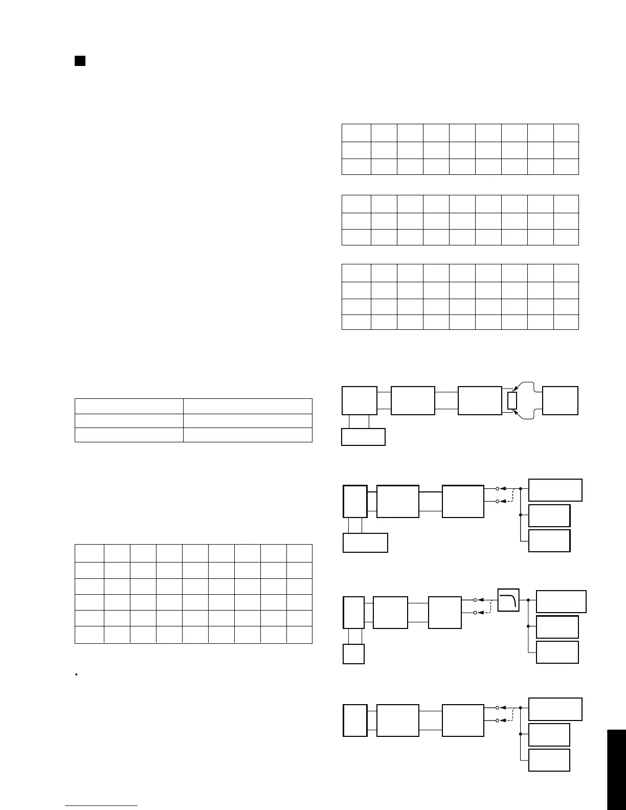
<POWER SUPPLY CHECK>
Check that the voltage obtained across each test point
and ground on the tuner circuit is as follows.
Test points Rating or Standard
+5 V terminal +5.6 ±0.5 V
-VP terminal -23.0 ±1.0 V
CAUTION :
Before setting to the TEST mode, write down the user
preset memory content in the table as shown below. (This
is because setting to the TEST mode will cause the
memory content to be the factory preset memory content,
i.e. all the user preset memory content will be erased.)
<User preset memory content>
Preset keys
P1 P2 P3 P4 P5 P6 P7 P8
A
B
C
D
E
<TEST mode>
Turn on the POWER switch while pressing the A/B/C/D/
E and FM/AM(FM/MW/LW) keys simultaneously, and
the unit enters the TEST mode for the display check.
After this, repeat (1) to (4).
(1)All the segments on the display light up.
(2)The model name, TX-497 is displayed.
(3)The place of destination is displayed.
(4)The µCOM-version is displayed.
Pressing the P1 key will cause operation to start from (1).
Pressing any other key will cause the mode to return to the
NORMAL mode.
B, G, E models
<Factory preset memory content>
Preset
P1 P2 P3 P4 P5 P6 P7 P8
A, E 87.50 90.10 95.10 98.10 108.00 88.10 106.10 108.00
B, D 630 1080 1440 531 1711 900 1350 1400
C 153 171 225 270 288 180 207 252
<Connection Diagram (Measuring Instruments)>
1) Discriminator balance adjustment
2) Monaural distortion adjustment
3) Stereo distortion adjustment
4) Sensitivity verification
A, L, R models
Preset
P1 P2 P3 P4 P5 P6 P7 P8
A, C, E 87.50 90.10 95.10 98.10 108.00 88.10 106.10 108.00
B, D 630 1080 1440 531 1611 900 1350 1404
U, C models
Preset
P1 P2 P3 P4 P5 P6 P7 P8
A, C, E 87.5 90.1 95.1 98.1 107.9 88.1 106.1 107.9
B, D 630 1080 1440 530 1710 900 1350 1400