Do you have a question about the Yamaha WaveRunner VXR VX1800A and is the answer not in the manual?
Procedures and precautions for safe operation, covering rotating parts, hot parts, and electrical hazards.
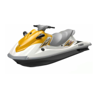
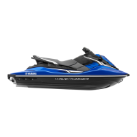
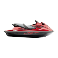
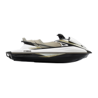
Key specifications including model codes, dimensions, weight, performance, engine, and drive unit details.
Specifications for the engine, cylinder head, camshaft, and valve system components.
Electrical specifications for ignition, charging, control, fuel, starting, and meter systems.
Recommended maintenance intervals based on operating hours or time, with corresponding operations and page references.
Procedures for routine checks of fuel lines, oil, spark plugs, battery, steering, and other components.
Procedures for checking compression pressure and performing engine unit adjustments.
Procedures for camshaft removal, check, installation, and valve clearance adjustment.
Procedures for valve and valve spring disassembly, check, measurement, and assembly.
Procedures for crankcase disassembly, connecting rod/piston removal, checks, and assembly.
Procedures for jet pump unit removal, impeller check, and installation.
Procedures for disassembling and assembling the impeller, drive shaft, and impeller duct components.
Procedures for checking electrical components using YDIS, power supply, peak voltage, and test leads.
Checks for ignition spark, ignition coil output voltage, and pickup coil resistance.
Procedures for checking stator coil output voltage, resistance, and rectifier/regulator voltage.
Checks for oil pressure switch, thermo switch, thermo sensor, engine temp sensor, and intake sensors.
Procedures for checking fuel injectors, fuel pump relay, and fuel pump module operation.
Checks for fuses, handlebar switches, main relay continuity, and starter relay checks.
Procedures for RiDE motor removal, installation, and RiDE system initialization.
Guidelines for troubleshooting engine unit issues using YDIS and self-diagnosis.
Detailed steps for diagnosing specific engine unit issues based on diagnostic codes.
Troubleshooting procedures for engine issues when no diagnostic codes are available.
| Model | WaveRunner VXR VX1800A |
|---|---|
| Seating Capacity | 3 |
| Starting System | Electric |
| Displacement | 1812cc |
| Fuel Type | Unleaded gasoline |
| Fuel Delivery System | Electronic Fuel Injection |
| Rider Capacity | 3 |
| Bore x Stroke | 86 mm x 78 mm |
| Fuel Capacity | 70.8 L (18.7 US gal) |
| Height | 1.19 m (47 in) |
| Dry Weight | 385 kg (849 lb) |