5-75
Crankcase, connecting rod, and piston
Crankcase disassembly
1. Place the crankcase upside down on a
bench.
2. Remove the crankcase “1”.
• Loosen the crankcase bolts in the opposite
order used for tightening.
• The numbers embossed on the crankcase
indicate the crankcase tightening order.
• Insert a flat-head screwdriver between the
reinforced portions “a” of the cylinder block
“2” and the crankcase “1” to separate them.
• Work carefully and make sure that the cylin-
der block and crankcase separate evenly.
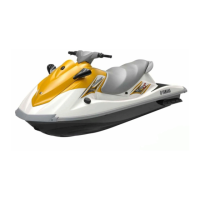
3. Remove the crankshaft bearings “1” from
the crankcase.
Write down the position of each crankshaft
bearing “1” so that it can be installed in its orig-
inal position.
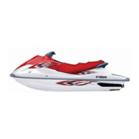
Connecting rod and piston removal
1. Remove the connecting rod cap “1”, and
then remove the connecting rod bearings
“2” and piston and connecting rod “3”.
For reference during installation, make identifi-
cation marks “a” on the connecting rod cap,
connecting rod, connecting rod bearings, and
piston crown.
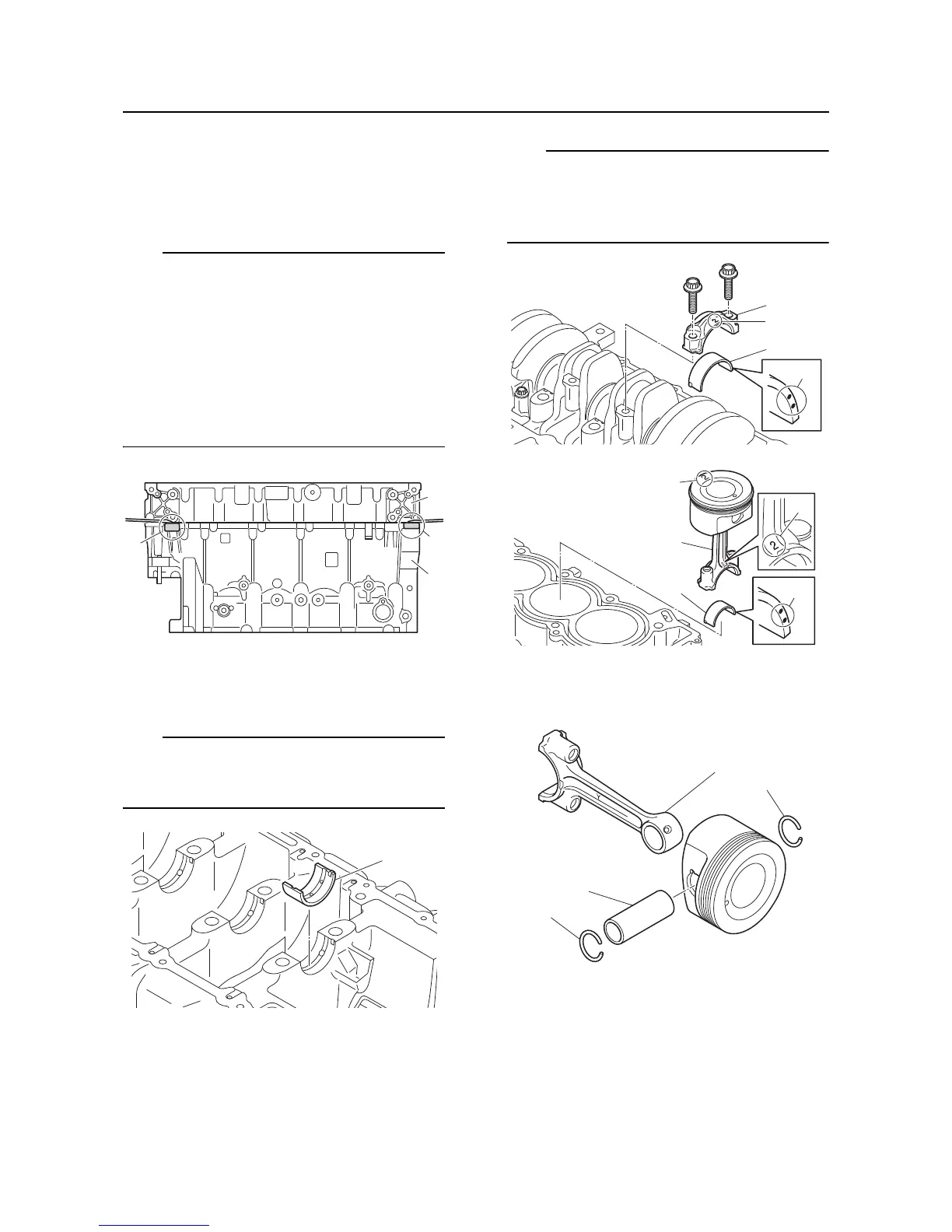
2. Remove the piston pin clips “1”, piston pin
“2”, and connecting rod “3”.
3. Remove the piston rings.
Crankcase check
1. Check the oil passages. Blow out using
compressed air if there are obstructions.
 Loading...