–18–
EBA00038
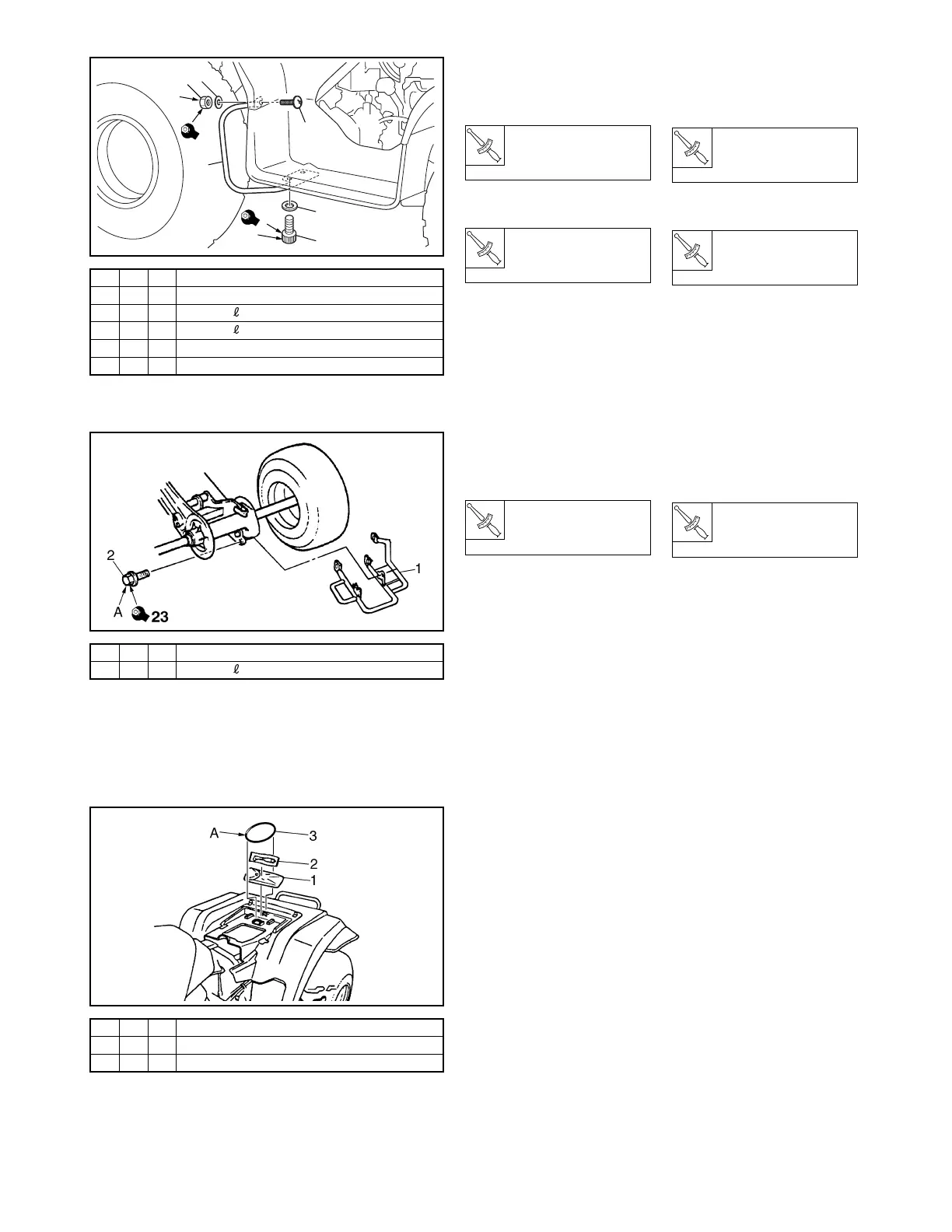
16. FENDER STAYS
A: Tighten the bolts to specifica-
tion.
B: Tighten the nuts to specifica-
tion.
T
R
.
.
Bolt
7 Nm
(0.7 m · kg, 5.1 ft · lb)
T
R
.
.
Nut
4 Nm
(0.4 m · kg, 2.9 ft · lb)
EBA00041
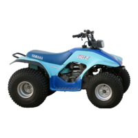
17. SWINGARM GUARD
A: Tighten the bolts to specifica-
tion.
T
R
.
.
Bolt
23 Nm
(2.3 m · kg, 17 ft · lb)
EBA00048
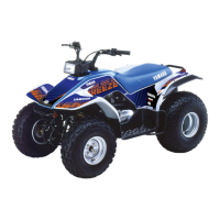
18. OWNER’S TOOL KIT
A: Secure the air gauge and the
owner’s tool kit to the rear
fender with the band.
FBA00038
16. SUPPORTS DE GARDE-
BOUE
A: Serrer les vis au couple spécifié.
B: Serrer les écrous au couple spéci-
fié.
T
R
.
.
Vis
7 Nm
(0,7 m · kg, 5,1 ft · lb)
T
R
.
.
Écrou
4 Nm
(0,4 m · kg, 2,9 ft · lb)
FBA00041
17. GARDE DE BRAS
OSCILLANT
A: Serrer les vis au couple spécifié.
T
R
.
.
Vis
23 Nm
(2,3 m · kg, 17 ft · lb)
FBA00048
18. TROUSSE DE
RÉPARATION
A: Attacher le manomètre et la
trousse de réparation au garde-
boue arrière à l’aide de l’anneau
en caoutchouc.
1S2
2 (4)-V 4
D = 13 (0.51), d = 7 (0.28)
3 (4)-V 4
d = 6 (0.24), = 12 (0.47)
4 (4)-V 2
d = 5 (0.20), = 18 (0.71)
5 (4)-V 2
D = 14 (0.55), d = 6 (0.24)
6 (4)-V 2
d = 5 (0.20)
B
6
5
4
2
3
1
A
4
7
1(4)-C1
2 (4)-V 5
d = 8 (0.31), = 16 (0.63)
1 (4)-V 1
2 (4)-V 1
3 (4)-V 1