ALTERNATOR
11-8
TNV IDI Service Manual
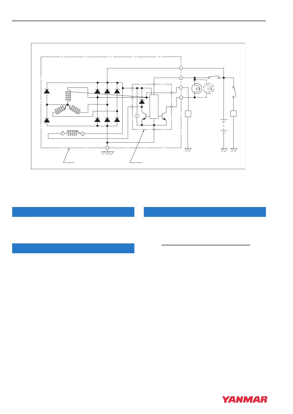
Alternator Wiring Diagram
ALTERNATOR WIRING DIAGRAM
1–Key Switch
2 –Charge Lamp (3.4 Watts Max.)
3 –Load
4–Battery
5 –Alternator Assembly
6 –IC Regulator Assembly
Figure 11-2
Do not short-circuit the charging system between
alternator terminals IG and L. Damage to the
alternator will result.
Do not connect a load between alternator terminals
L and E. Damage to the alternator will result.
Do not remove the positive (+) battery cable from
alternator terminal B while the engine is operating.
Damage to the alternator will result.
L
IG
B
P
L
IG
IC
B
F
E
0.5µF
E
PI
P
1
5
6
2
4
33
B
A
T
TNV_IDI_ServiceManual_A4.book 8 ページ 2012年2月24日 金曜日 午前10時24分



 To Next Page