Do you have a question about the Yanmar 3TNV84 and is the answer not in the manual?
Details the coverage, period, owner's obligations, limitations, and exclusions of the Yanmar limited warranty.
Outlines the specific warranty coverage and terms for the engine's emission control system, particularly for US markets.
Explains the meaning and usage of DANGER, WARNING, and CAUTION safety alert symbols and statements.
Lists specific safety precautions related to hazards like scald, explosion, fire, crush, and entanglement.
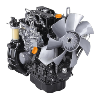
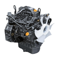
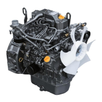
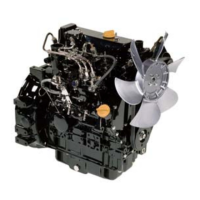
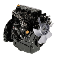
Illustrates and identifies the major components of the Yanmar TNV series engines.
Details EPA/ARB regulations and explains the emission control labels found on Yanmar TNV engines.
Describes the function of key engine components, including the air cleaner, alternator, and fuel system parts.
Explains the function and features of electronic control system components like E-ECU and Eco-governor.
Details the function of components within the engine cooling system, such as the radiator and thermostat.
Provides specifications and requirements for diesel fuel, including bio-diesel and additional technical requirements.
Covers engine oil specifications, viscosity, checking, adding, and typical capacities for various Yanmar TNV engines.
Details engine coolant specifications, including types, mixing, and replacement intervals.
Explains the engine model number description, speed specifications, and general engine specifications.
Provides essential safety warnings and precautions before performing any periodic maintenance.
Outlines specific maintenance tasks for different operating hour intervals, starting with the initial 50 hours.
Details the initial maintenance tasks to be performed after the first 50 hours of engine operation.
Lists maintenance tasks to be performed every 50 hours of engine operation, including fuel filter and battery checks.
Outlines maintenance tasks required every 250 hours, such as draining the fuel tank and replacing oil filters.
Details maintenance tasks for every 500 hours, including replacing air and fuel filters.
Specifies maintenance tasks for every 1000 hours, including cooling system flush and valve clearance adjustment.
Lists maintenance tasks for every 1500 hours, such as inspecting fuel injectors and EGR valve.
Outlines maintenance tasks for every 2000 hours, including checking fuel and coolant hoses and lapping valves.
Provides critical safety warnings and precautions before servicing engine components.
Lists specifications for valve clearance, valve recession, and valve seat angles for cylinder heads.
Details the inspection of push rods for bend and measurement of their clearance.
Covers inspection of rocker arm shaft hole diameter and outside diameter.
Provides specifications for valve spring free length and squareness.
Details specifications for camshaft end play, bend, lobe height, and bearing clearances.
Lists specifications for crankshaft journal diameters, oil clearance, and end play.
Provides specifications for piston outside diameter, diameter measurement location, and pin bore diameter.
Lists specifications for piston ring groove width, width, side clearance, and end gap.
Provides specifications for connecting rod small and big end dimensions and oil clearance.
Details specifications for tappet bore diameter, stem diameter, and oil clearance.
Lists specifications for cylinder inside diameter and bore taper.
Provides torque values for various bolts and nuts used in engine assembly.
Lists and describes various measuring instruments used for engine service.
Outlines critical safety warnings and precautions related to fuel system servicing, including fuel handling and ECU misuse.
Introduces the MP fuel injection pump, its components, types, and features.
Details the MP fuel injection pump, its components, types, and service requirements.
Explains the function and operation of the stop solenoid in the fuel injection pump and its failure modes.
Describes the function and operation of the cold start device (CSD) for improving engine starting at low temperatures.
Explains the operation of the electronically controlled governor (Eco Governor) and its components in engine speed control.
Provides special torque chart and test/adjustment specifications for fuel system components like injectors and pumps.
Illustrates the components and flow of the diesel fuel system, including tank, filters, and injectors.
Identifies and lists the fuel system components for 2-valve and 4-valve cylinder heads.
Details the procedures for removing and installing the MP fuel injection pump, including timing adjustments.
Explains how to determine and adjust the fuel injection timing for optimal engine performance.
Covers the removal, testing, disassembly, inspection, and installation of fuel injectors.
Provides critical safety warnings and precautions before servicing the cooling system components.
Introduces the service procedures for the 4TNV84 engine coolant pump.
Illustrates the components and flow of the engine cooling system, including the radiator and coolant pump.
Identifies and lists the components of the engine coolant pump assembly.
Details how to check the engine coolant system for leaks using a cooling system tester.
Covers the removal, disassembly, cleaning, inspection, reassembly, and installation of the engine coolant pump.
Provides critical safety warnings and precautions before servicing the lubrication system components.
Introduces the service procedures for the trochoid oil pumps used in various Yanmar TNV engines.
Provides information on engine oil pressure and oil pump specifications.
Details the components and service information for the trochoid oil pumps.
Outlines the steps for disassembling the oil pump assembly from the gear case cover.
Describes how to clean and inspect oil pump components for wear or damage, including clearance measurements.
Details the procedures for reassembling the oil pump assembly, including lubrication and torque specifications.
Provides critical safety warnings and precautions before servicing the turbocharger.
Introduces the service information and specifications for Yanmar RHF5, RHB31, and RHB51 model turbochargers.
Covers common problems related to turbochargers like excessive exhaust smoke, oil consumption, and poor response.
Identifies and illustrates the various components of the turbocharger assembly.
Explains the theory of operation and function of turbocharger components like turbine, compressor, and waste gate.
Details the procedure for washing the turbocharger compressor impeller using blower wash fluid or water.
Outlines the schedule and procedures for periodic inspection of the turbocharger, including visual checks and rotor play.
Explains how to check rotor end play and run-out for the turbocharger using a dial indicator.
Details the procedure for testing the waste gate valve operation to ensure proper engine performance.
Explains how to perform a leak test on the waste gate actuator to verify its integrity.
Covers the steps for installing the turbocharger onto the exhaust manifold and connecting oil lines.
Provides critical safety warnings and precautions before servicing the starter motor components.
Introduces the starter motor and provides information on standard and optional models.
Lists specifications for various Yanmar starter motors, including part numbers, voltage, and performance data.
Details technical specifications for a representative starter motor, covering electrical, mechanical, and performance data.
Offers a flowchart for diagnosing and troubleshooting common starter motor problems, from battery to engine issues.
Identifies and illustrates the various components of the starter motor assembly with numbered parts.
Covers the removal, disassembly, cleaning, inspection, reassembly, and installation of the starter motor.
Explains how to check and adjust the pinion projection length for proper starter engagement.
Details the procedure for performing a no-load test on the starter motor to check its performance characteristics.
Provides critical safety warnings and precautions before servicing the alternator or dynamo components.
Introduces the service procedures for the dynamos and alternators, referencing specific Yanmar part numbers.
Lists standard and optional dynamo and alternator models with their specifications.
Provides detailed specifications for the Yanmar alternator, including output, voltage, and dimensions.
Provides detailed specifications for the Yanmar dynamo, including output, voltage, and dimensions.
Offers a troubleshooting guide for common alternator problems, such as battery indicator issues and voltage variations.
Identifies and illustrates the various components of the alternator assembly.
Presents the wiring diagram for the alternator, showing connections to key components like battery and key switch.
Shows the standard output characteristics of the alternator based on RPM and ambient temperature.
Covers the removal, disassembly, reassembly, and installation of the alternator assembly.
Identifies and illustrates the components of the dynamo assembly.
Presents the wiring diagram for the dynamo, showing its electrical connections and operation.
Explains the basic operation of the dynamo, including the role of magnets, stator, and current limiter.
Displays the standard output characteristics of the dynamo based on alternator speed.
Details tests for stator coil continuity, short-to-ground, and regulated output.
Lists the specific Yanmar engine models that are equipped with the electronic control system.
Provides critical safety warnings and precautions before servicing the electronic control system components.
Explains the features and operation of the electronic engine control system, including EGR and governor functions.
Provides diagrams and information on the electronic control system's harness connections for proper setup.
Outlines essential precautions to prevent electrical component failure and warranty issues related to wiring.
Provides a table of electrical wire resistance values based on AWG size and metric nominal area.
Lists maximum total battery cable lengths for different starter motor outputs based on AWG size.
Provides charts for selecting electrical wire sizes to minimize voltage drop in circuits.
Offers a conversion table between AWG wire sizes and European standards for conductor diameter and area.