(5) Attach the
(3)
grease nipple.
NOTES:
a)
iPhe plate should be parallel to the center when
press-firting the (4) bushing.
b) The (7) castle nut should be fastened so there is no
play
benveen the
(I)
front axle bracket and the (2)
front
axle, furthermore the front arle should swing
smoothly.
C) Insert
the (5) center pin after it has been completely
greased.
d) Be sure
rhar the (8) cotrer pin 4
x
30 of the (5)
cenrer pin
is
placed in the hole horizontaNy, as shown
in
the iNusnation
Do not place it in the vemmcaI
position
e) (4) bushing (2
pcs) length:
0.9449
in
(24 mm)
-
YMI55
0.9843
in
(2.5
mm)
-
YM135
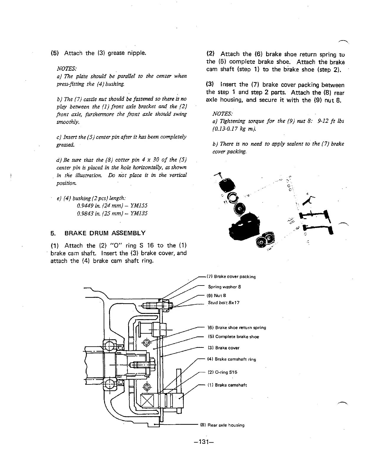
5.
BRAKE DRUM ASSEMBLY
(1)
Attach the
(2)
"0"
ring
S
16 to the (1)
brake cam shaft. Insert the
(3)
brake cover, and
attach the
(4)
brake
cam
shaft ring.
(2)
Attach the (6) brake shoe return spring
10
the (5) complete brake shoe. Attach the brake
cam shaft (step
1)
to the brake shoe (step 2).
(3)
Insert the
(7)
brake cover packing between
the step
1
and step 2 parts. Attach the (8) rear
axle housing, and secure
it
with the
(9)
nut 8.
NOTES:
a) Tightening torque for the (9) nut 8: 9-12 fr lbs
(0.13-0. 17 kg
m).
b) There is no need to apply sealent ro the
(7)
brake
cover
packing.
171 Brake
cover
packing
Spring
washer 8
(91
Nut
8
Stud
bolt8x17
16)
Brake shoe return
spring
IS1
Complete
brake
shoe
I31 Brake cover
(41 Brake camshair
ring
12)
O-ring
516
Ill
Brake camshaft
(81
Rear
axle
housing