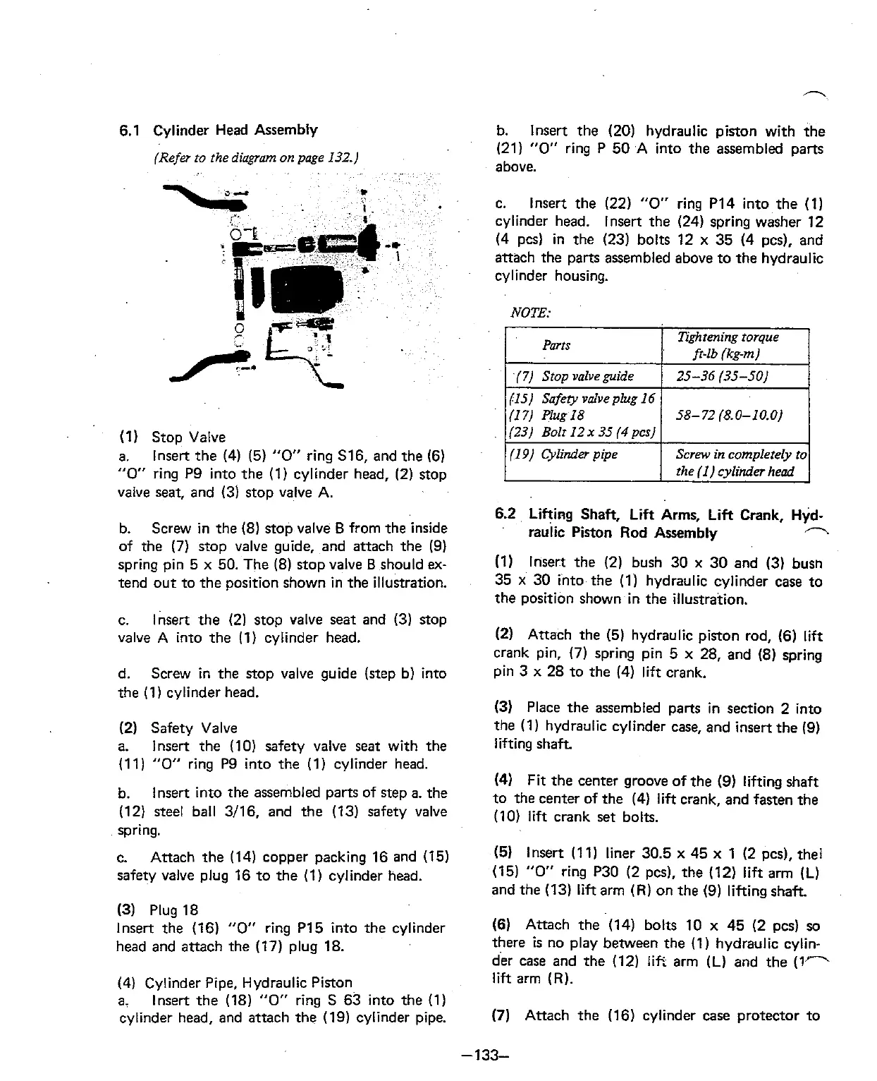
Cylinder Head Assembly
(Refer ro the
diagram
on page 132.)
(1) Stop Valve
a.
lnsert the
(4) (5)
"0
ring S16, and the (6)
"0"
ring P9 into the (I) cylinder head, (2) stop
valve seat, and
(3) stop valve A.
b. Screw in the (8) stop valve
B
from the inside
of the
(7)
stop valve guide, and attach the (9)
spring pin 5
x
50. The (8) stop valve
B
should ex-
tend out to the position shown in the illustration.
c. lnsert the (2) stop valve seat and (3) stop
valve A into the
(1) cylinder head.
d. Screw in the stop valve guide (step
b) into
the
(1) cylinder head.
(2)
Safety Valve
a. lnsert the (10) safety valve seat with the
(11)
"0"
ring P9 into the (1) cylinder head.
b.
lnsert into the assembled parts of step a. the
(12) steel ball 3/16, and the (13) safety valve
spring.
c.
Attach the (14) copper packing 16 and
(15)
safety valve plug 16 to the (1) cylinder head.
(3)
Plug 18
lnsert the (16)
"0"
ring PI5 into the cylinder
head and attach the
(17) plug 18.
(4) Cylinder Pipe, Hydraulic Piston
a,
lnsert the (18)
"0"
ring S 63 into the (1)
cylinder head, and attach the (19) cylinder pipe.
b. lnsert the (20) hydraulic piston with the
(21)
"0"
ring P 50 A into the assembled parts
above.
c.
lnsert the
(22)
"0"
ring PI4 into the (1)
cylinder head.
lnsert the (24) spring washer 12
(4 pcs) in the (23) bolts 12 x 35 (4 pcs), and
attach the parts assembled above to the hydraulic
cylinder housing.
NOTE:
6.2 Lifting Shaft,
Lift
Arms, Lift Crank, Hyd-
raulic Piston Rod
Asembly
h
Parts
(7)
Srop valve guide
(15) Safety v~alve plug I6
(1
7)
Plug 18
(23) Bolt 12
x
35
(4
pcs)
(19) Cylinder pipe
(1)
lnsert the
(2)
bush 30
x
30 and (3) busn
35
x
30 into the (1) hydraulic cylinder case to
the position shown in the illustration.
Tighrming torque
fr-lb (kg-m)
25-36 (35-50)
58-72 (8.0-10.0)
Screw in
complerely to
the
(I)
cylinder head
(2)
Attach the (5) hydraulic piston rod, (6)
lift
crank pin, (7) spring pin
5
x 28, and (8) spring
pin
3
x
28 to the (4) lift crank.
(3)
Place the assembled parts in section 2 into
the
(1) hydraulic cylinder case, and insert the (9)
lifting shaft
(4)
Fit the center groove of the (9) lifting shaft
to the center of the
(4)
lift
crank, and fasten the
(10) lift crank set bolts.
(5) lnsert (1 1) liner 30.5 x 45 x 1 (2 pcs), thei
(15)
"0"
ring P30 (2 pcs), the (12)
lift
arm (L)
and the (13)
lift
arm (R) on the (9) lifting shaft.
(6) Attach the (14) bolts 10 x 45 (2 pcs)
so
there
is
no play between the (1) hydraulic cylin-
der case and the (12)
li?.
arm (L) and the
(1-
lift
arm (R).
(7)
Attach the (16) cylinder case protector to