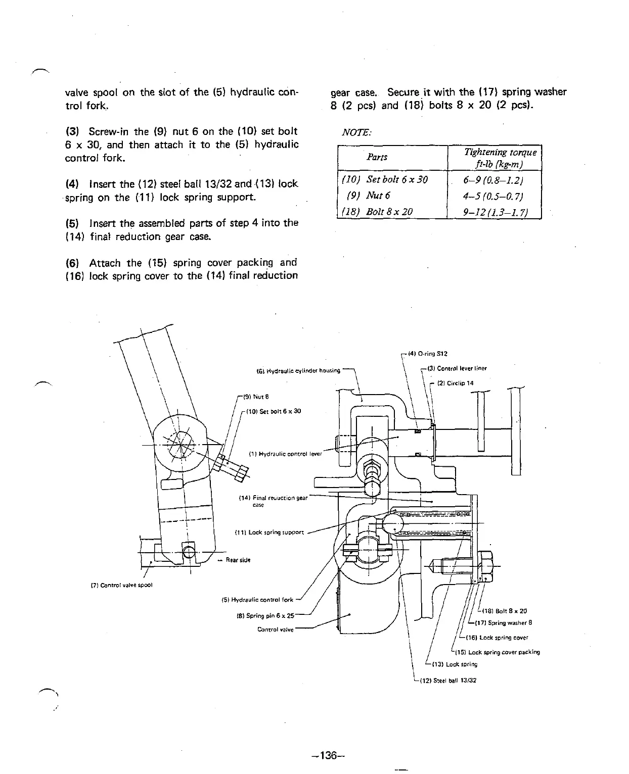
valve spool on the slot of the (5) hydraulic con-
gear case. Secure
it
with the
(17)
spring washer
trol fork.
8 (2 pcs) and (18) bolts
8
x
20 (2 pcs).
(3)
Screw-in the
(9)
nut
6
on the (10) set bolt
NOTE
6
x
30, and then attach
it
to the
(5)
hydraulic
control fork.
(4)
Insert the (12) steel ball 13/32 and (13) lock
spring on the
(1 1) lock spring support.
(5)
Insert the assembled parts of step 4 into the
(14) final reduction gear case.
(10) Set bolt
6
x
30
6-9
(0.8-1.2)
(9)
Nut
6
4-5
(0.5-0.7)
(6)
Attach the (15) spring cover packing and
(16)
lock spring cover to the (14) final reduction