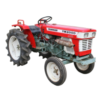
6.3 Control Valve Assembly
(1)
Insert the (2)
seal
washer and the(3)
"0"
ring PI4 into the
(1)
hydrauliccylinder case.
(2)
lnsert the (5)
"0"
ring PI4
(2
pcs) into the
(4) control valve.
(3) Attach the assembled parts of step
2
to the
parts of step 1, and secure with the (6)
(7)
con-
trol valve set bolts
(2
pcs).
NOTES:
a) Tighten the (6)
(7)
control valve set bolts
(2
pcs)
unformly to the required torque.
b) Torque for
the (6)
(7)
control valve set bolts:
33-40
ft-lbs (4.5-5.5 kern)
c)
DO
NOT
rum
or take
opart
the nut or spindle that
is
attnched to the borrom of the
(4)
control valve.
/Cylinder
head
/
Do
not
disassemble
this
portion
during
regular
inspection.
6.4 Hydraulic Control Fork, Hydraulic Control
(2)
Place the
(5)
hydraulic control fork in the
Lever Assembly
(6)
hydraulic cylinder case. Insert the assembled
parts in step 1 in the (6) hydraulic cylinder
cawh
(1)
Attach the (2) circlip 14 to the (1) hydraulic
and the
(5) hydraulic control fork.
Be
sure
tc
control lever, and insert the (3) control lever liner
place the
(8)
spring pin
6
x
25 of the
(7)
control
and the
(4)
"0"
ring 512.