-
d-iption
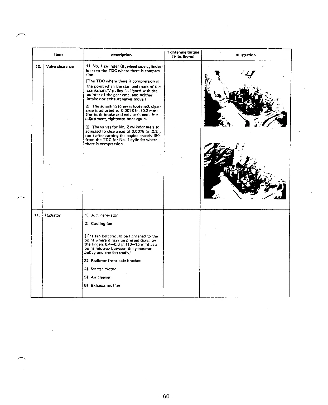
1)
No.
1
cylinder (flywheel ridecylinderl
is set to the TDC where there ir comprer-
rion.
[The TDC where there
is
compression is
the point when the stamped mark of the
crankrhaftlv-pulley is aligned with the
Pointer of the gear
case,
and neither
intake
nor
exhaust valves move.)
2) The adjusting screw is loosened, clear-
ance is adjusted to 0.0078 in. 10.2 mm)
(for both intake and exhausti, and after
adjustment, tightened
once
again.
3)
The valves for No.
2
cylinder are also
adjusted to clearances of 0.0078 in (0.2
mml after turning the engine exactly 180
from the TDC
for
No.
1
cylinder where
there is comprerrion.
11
A.C. geneator
2) Cooling fan
[The fan belt should be rightened to the
point where
it
may be pressed down
by
the fingers 0.4-0.6 in (10-15 mmi at
a
point midway beween The generator
pulley and rhe
fan
shaft.]
31 Radiator front axle bracket
41 Starter motor
5) Air cleaner
6) Exhausr muffler
10.
11.
Item
Valve clearance
Radiator
Tightenirg torque
ft.lbr
kg-mi
lllunration
'Y
.
,-.