XK3190-A12(E)
7
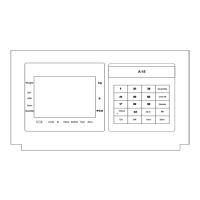
2.3 CONNECTION OF THE INDICATOR
2.3.1 The definition of the connectors on the PCB
(2-2) A12 main board connecting figure
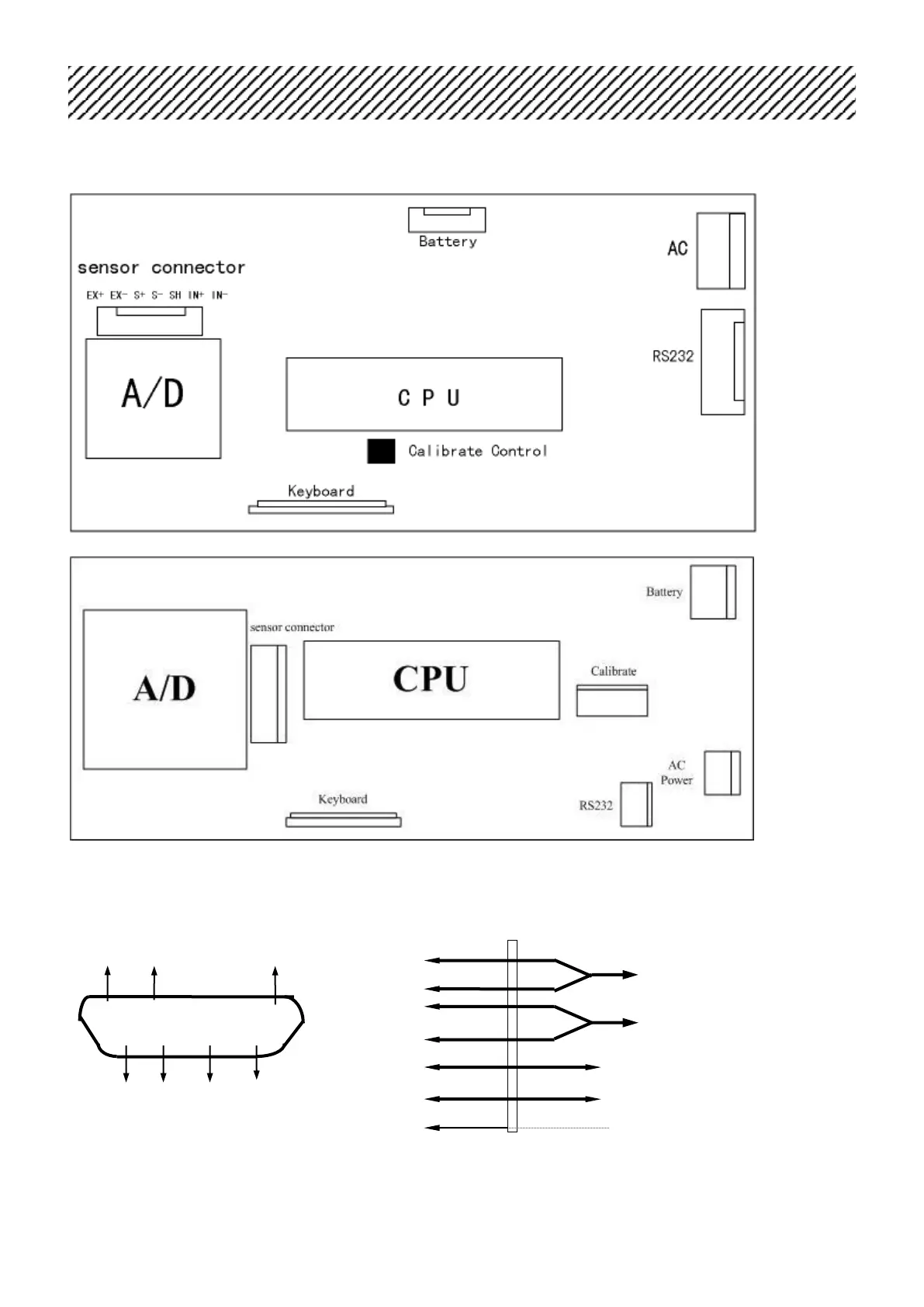
(2-3) A12E main board connecting figure
2.3.2 Load cell connection
indicator load cell
EX- S- SH ⑥ EX+ Excitation+
⑦ S+
① ②
⑥ ⑦
③ ④
⑧ ⑨
⑤ ②
S-
① EX-
⑨ IN+
EX+ S+ IN- IN+ ⑧ IN-
Excitation-
Load cell output signal+
load cell output signal-
⑤ SH shield
 Loading...