12
Flameout wires MUST be connected for correct engine operation. Failure to
connect can result in serious injury.
1. Remove all parts and packaging components.
2. Use a utility knife to cut all 4 vertical edges and lay the side panels at
around the edger.
3. Remove any remaining packaging.
4. Roll the unit out from the carton, and place on a hard level surface.
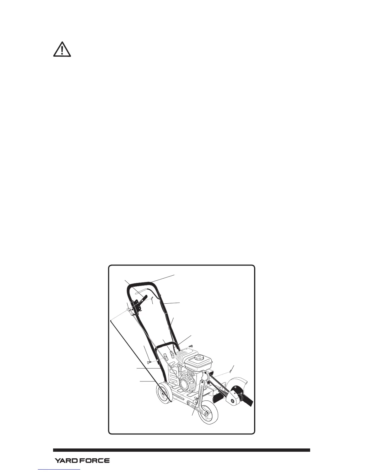
NOTE: Refer to Figure 2 when following steps below:
1. Assemble the upper handle to the lower handle with the (2) pipe bolts and
the (2) plastic wing nuts. Firmly handtighten the wing nuts.
2. Slide one end of the control rod into the hole of the Depth Control Lever.
Secure with hairpin.
3. Slide the other end of the control rod through the hole of the wheel bracket
arm. Secure with second hairpin.
4. Attach the recoil starter handle through the rope guide, by twisting it into
position.
5. Remove the temporary insert from the engine ameout wire terminal.
6. Connect the ameout wires from the engine and handle. Use cable tie to
secure loose wire to handle.
Upper Handle
Lower
Handle
Hair Pin
Control Rod
Wheel Bracket
Arm
Hair Pin
Pipe Bolt
Figure 2
Depth Control
Lever
Recoil
Starter
Handle
Plastic
Wing Nut
Handle Flameout Wire
Engine Flameout Wire
Connection Terminal