15 support@yardistrystructures.com
Step 2: Post Assemblies
HardwareWood Parts
F2.2
(422) Plinth
Top
Bottom
#8 x 1-1/2” Wood Screws
(x 2 per Post Mount, from
bottom)
#8 x 1-1/2”
Wood Screws
(x 4 per Plinth)
Post
Mount
F2.3
16 x #10 x 1-1/4” Pan Screw
80 x #8 x 1-1/2” Wood Screw
8 x Post Mount
8 x 5/16” T-Nut
8 x 5/16 x 1-1/4” Hex Bolt
(with 5/16” lock washer, 1/4-5/16” large washer)
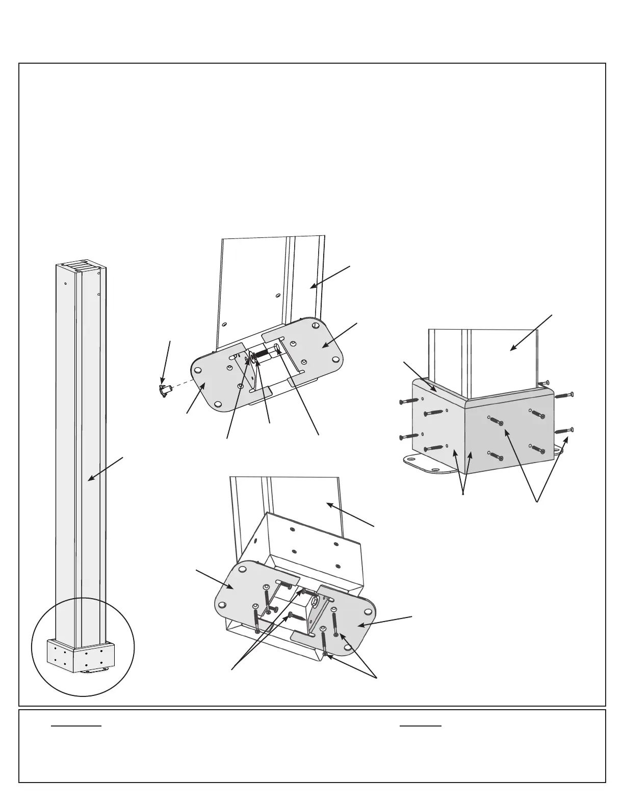
F2.1
Post
Mount
Rounded
Edge on Top
F2.4
Post
Mount
#10 x 1-1/4” Pan Screws (x 2
per Post Mount, from inside)
1/4 - 5/16”
Large Washer
5/16” Lock
Washer
5/16 x 1-1/4”
Hex Bolt
5/16” T-Nut (x 2
per Post)
Post
Mount
A: At the bottom of four (1018) M Posts insert two 5/16” T-Nuts as shown in F2.1 and F2.2.
B: At the bottom of each (1018) M Post place two Post Mounts tight to the bottom and inside faces as shown in
F2.1 and F2.2. Loosely attach with one 5/16 x 1-1/4” Hex Bolt (with 5/16” lock washer and 1/4-5/16” large washer)
per mount so they connect to the T-Nuts.
C: On each side of the Posts, place one (422) Plinth ush to the bottom and attach with four #8 x 1-1/2” Wood
Screws per plinth. Rounded edges on top. (F2.1 and F2.3)
D: From the bottom of each Post Mount attach to posts with two #8 x 1-1/2” Wood Screws per mount and then from
the inside with two #10 x 1-1/4” Pan Screws per mount These screws are installed at a slight angle. Tighten all
bolts. There will be four M Post Assemblies. (F2.4)
4 x (1018) M Post
16 x (422) Plinth
(1018) M Post
(1018) M Post
(1018) M
Post
(1018) M Post