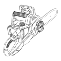
d. Place the chain drive links into the guide bar
groove. Position the chain so there is a loop at
the back of the guide bar.
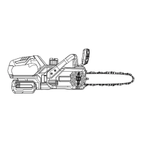
e. Hold Chain in position on the guide bar and
place the loop around the sprocket of the power
head.
f. Place the guide bar on the mounting surface
by sliding the guide bar slot over the alignment
pin is inserted in the lower hole in the tail of the
bar.
g. Replace the side cover and lightly tighten the
side cover knob by turning it clockwise. The bar
must be free to move for tension adjustment.
h. Remove all the slack from the chain by turning
the chain-tensioning knob clockwise until the
chain seats snugly against the guide bar with the
drive links in the guide bar groove.
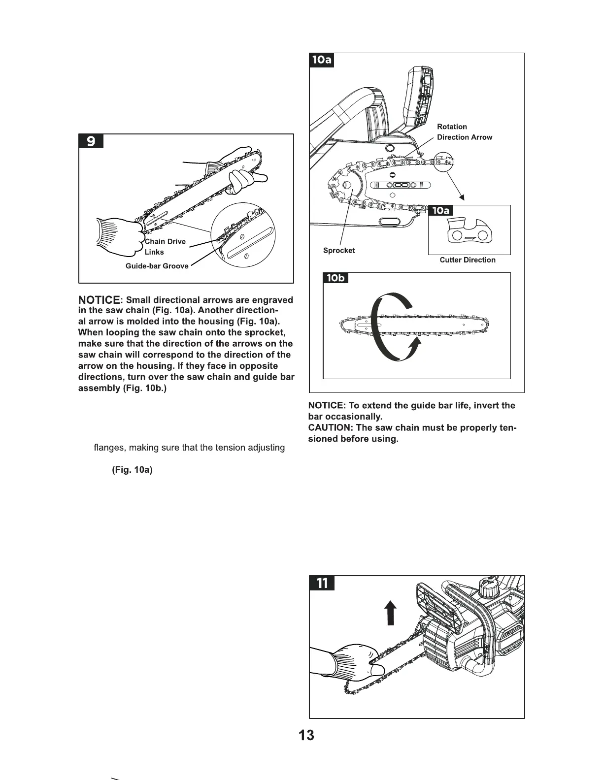
i. Lift the tip of the guide bar up to check for sag
(Fig. 11). Release the tip of the guide bar and
turn the chain-tensioning knob once clockwise.
Repeat this process until the sag is eliminated.