model no. 060-1983-0 | contact us: 1.866.523.5218 model no. 060-1983-0 | contact us: 1.866.523.5218
11
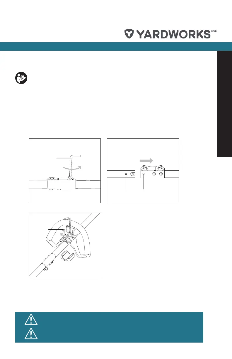
1. ASSEMBLING THE UPPER SHAFT AND LOWER SHAFT
1) Loosen the bolt on the connector. (see Fig. A1.)
2) Align and insert the lower shaft directly into the upper shaft. (see Fig. A2.)
3) Position the locking/release button into the guide recess. (see Fig. A2.)
2. ASSEMBLING THE AUXILIARY HANDLE
Place the auxiliary handle onto the shaft from the top, align with the anti-vibration circle on the
shaft, insert the screws into the four holes, and tighten them with the wrench. (see Fig. B.)
To reduce the risk of injury, user must read instruction manual
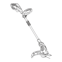
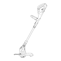
Intended Use
The machine is intended for the cutting of grass and weeds under bushes, as well as on
slopes and edges that cannot be reached with the lawn mower.
A2
A1
B
E
E
G1
F
G3
G2
H
G4
I2
I1
I4
I3
J1
J2
C2
C1
1
2
1
2
1
1
2
Locking/
Release knob
Guide recess
13
B
E
E
G1
F
G3
G2
H
G4
I2
I1
I4
I3
J1
J2
C2
C1
1
2
1
2
1
1
2
Locking/
Release knob
Guide recess
13
14
Assembly
CAUTION! The machine must not be operated before it has been
assembled completely.
CAUTION! Do not insert the battery until the appliance has been
completely assembled.
 Loading...