26
YASKAWA
|
YASKAWA AC Drive
CH700
Catalog
|
KAEP C710617 24
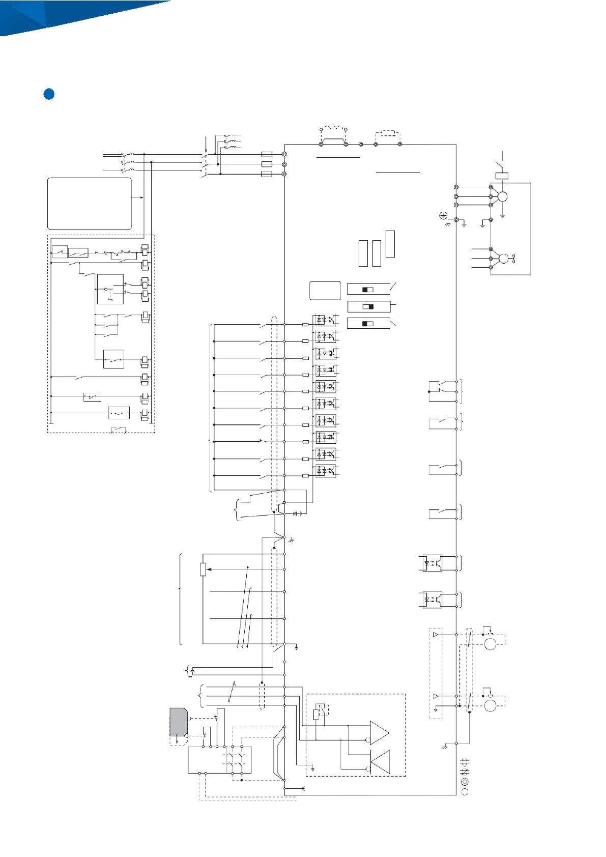
Standard Connection Diagram
Standard Connection Diagram
10 digital input, screw clamp terminal board type
DC Reactor
(
option
)
*
2
*
1
2MCCB
r1
s1
( )
U X
3
Jumper
Braking resistor unit
(
option
)
*
4
*
5
*
6
*
7
ELCB MCCB
Three
-
Phase
R
Power Supply
MC
t1
Fuse +
2
+
1
-
B 1
B 2
R/L 1
B Brake
Contactor
200
-
400 V
S
50/60 Hz
T
S/L 2
T/L 3
*
8
Main Circuit
The voltage rating of devices
used for a sequence circuit is
usually 200 V.
A separate transformer is
required when running from
a 400 V power supply to step
the voltage down to 200 V.
Emergency Main
*
9
Drive
Option Board
Connectors
U/T1
V/T2
W/T3
U
V
M
W
*
10
FLT
MC MB
THRX OFF ON R
F
MS
SA
MS
Main
r1
FU
s1
FV
M
MS
MC
FWD
STOP
REV
F
R
F
BRX
MC
Main Circuit Contactor
SA
SA
F Forward Run Command
R Reverse Run Command
SA
*
11
Control
Circuit
DIP Switch S4
A3 Analog/PTC
Input Selection[AI
DIP Switch S1
A2 Voltage/Current
t1
FW
Cooling Fan
R
Brake
B
Brake Contactor
SA
Forward RUN
Command
*
12 F
S1
Selection[I]
DIP Switch S2
B
Auto
-
hold
Reverse RUN Terminal Resistor
Brake Release
Command
BR
M1 M2 SA
B
Braking Resistor Unit
SA
Thermal Trip Contact
BRX
Brake Release
Command
BX
Brake
Release Check
Command
*
12 R
S2
External Fault
S3
Fault Reset
S4
Brake Release
Check
BX
S5
ON/OFF
[
OFF
]
FLT MA
Fault Relay Output
MB 250 Vac, max. 1 A
1 2
FLT
THRX
SA
TRX
Multi
-
step Speed 1
S6
30 Vdc, max. 1 A
MC
(
min. 5 Vdc, 10 mA
)
MC MA
SA
TRX
Multi
-
step Speed 2
S7
BR M1
M2
MFDO
250 Vac, max. 1 A
External Baseblock
30 Vdc, max. 1 A
Fault Relay Contact
Multi
-
function
Digital Inputs
(
default setting
)
(
N.C.
)
*
13
MS
Through Mode
Through Mode
S8
S9
S10
SN
SC
(
min. 5 Vdc, 10 mA
)
[
Default Setting
:
Brake Release Command
]
M3
MFDO
M4
250 Vac, max. 1 A
30 Vdc, max. 1 A
(
min. 5 Vdc, 10 mA
)
[
Default Setting
:
During Run
]
24 Vdc Power Supply Output
24 V
,
max. 150 mA
Frequency Setting
Potentiometer
*
23
SP
+24 V
*
14
E
(
G
)
Shield ground terminal
+V
*
15
M5
MFDO
250 Vac, max. 1 A
30 Vdc, max. 1 A
(
min. 5 Vdc, 10 mA
)
[
Default Setting
:
Speed Agree 1
]
P1
Multi
-
function
Analog Inputs
3
2 k▲
1
0 - 10 V
2
4 - 20 mA
0 - 10 V
Frequency Setting Power Supply
10.5 V max. 20 mA
A1
MFAI 1
[
Default Setting
:
Frequency Reference
]
-10
- +
10 V
(
20 k▲
)
/0
-
10 V
(
20 k▲
)
A2
MFAI 2
16
[
Default Setting
:
Frequency Bias
]
-10
- +
10 V
(
20 k▲
)
/0
-
10 V
(
20 k▲
)
0
-
20 mA
(
250
▲
)
/4
-
20 mA
(
250
▲
)
A3
MFAI 3/PTC Input
17
[
Default Setting
:
Auxiliary Frequency Reference 1
]
Multi
-
function
C1
Photocoupler Output
48 Vdc, max. 50 mA
[
Default Setting
:
Drive Ready
(
READY
)]
P2
Multi
-
function
C2
Photocoupler Output
48 Vdc, max. 50 mA
[
Default Setting
:
Alarms
]
FM
AC
-10
- +
10 V
(
20 k▲
)
/0
-
10 V
(
20 k▲
)
-
+
FM
0 V
15
Multi
-
function
*
19
24 Vdc Control Power
Input
18
-V Frequency Setting
Power
Su
p
*
ply,
DC
-
10.5 V
,
max. 20 mA
Analog Output 1
-10
-
+
10 V/0
-
10 V
24
Vd
*
c
700
mA
PS
External 24 Vdc Power Supply Input
(
max. 2 mA
)
:
MEMOBUS/Modbus
D
+
(
RTU mode
)
comm.
D
-
[
Default Setting
Output Frequency
]
AM
RS
-
485
Max. 115.2 kbps
AC
Termination resistor
(
120
▲
, 1/2 W
)
AC
- +
AM
Safety
Switch
S2
S1
Open
21
Safe Disable Inputs
H1
H2
DIP Switch S2
*
20
0 V
E
(
G
)
Multi
-
function
19
Analog Output 2
-10
-
+
10 V/0
-
10 V
(
max. 2 mA
)
[
Default Setting
:
Output Current
]
Safety
Controller
Reset /
Feedback
Input
EDM
Wire
Jumper
*
22
0
V
HC
SN
shielded line
twisted
-
pair shielded line
main circuit terminal
(
Safety Electronic Device Monitor
)
Connect to MFDO, Multi
-
function Photocoupler Output
control circuit terminal
 Loading...


