28
YASKAWA
|
YASKAWA AC Drive
CH700
Catalog
|
KAEP C710617 24
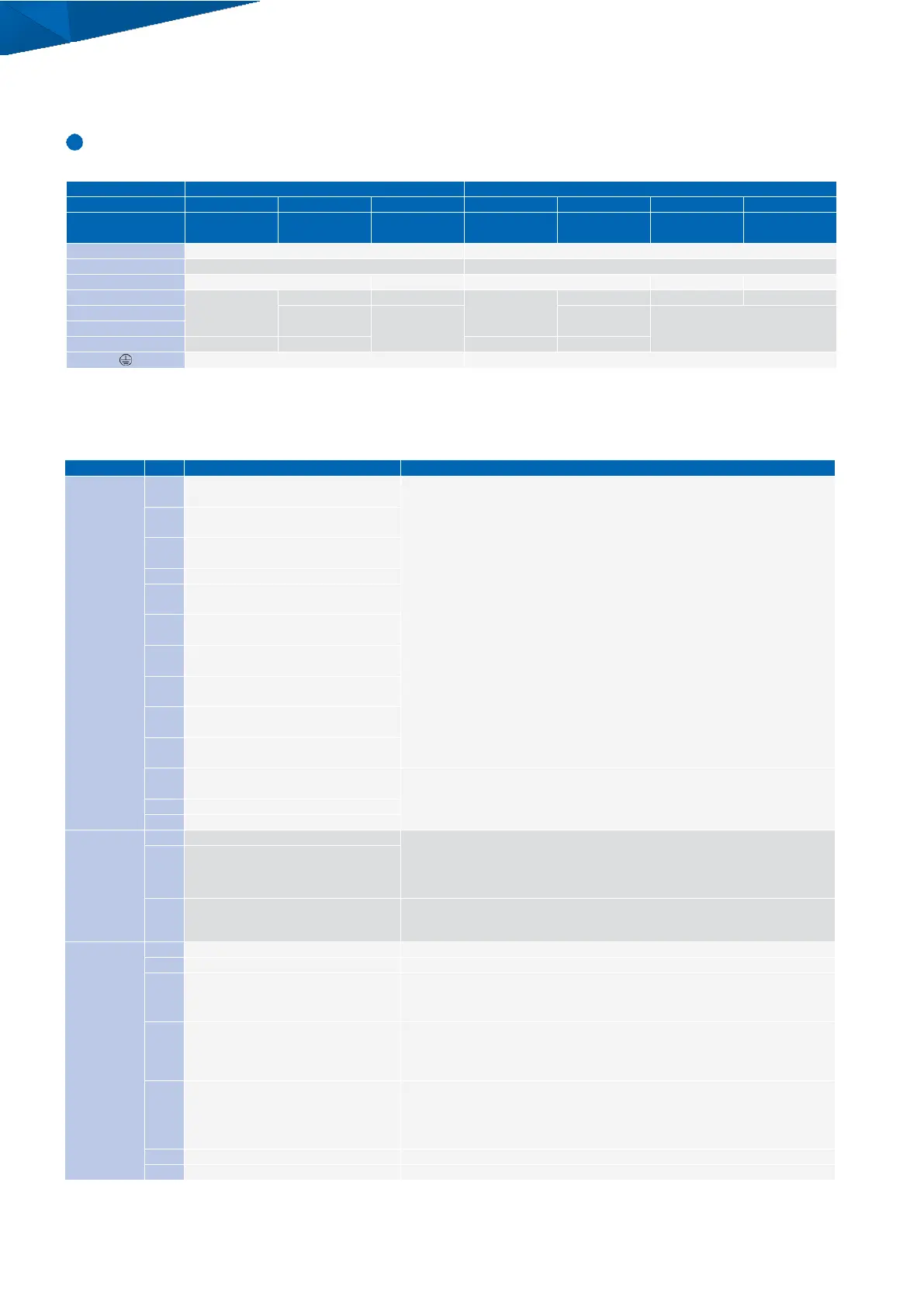
Terminal Functions
Main Circuit Terminals
Max. Applicable
Motor Capacity kW
Main circuit input power supply
Main circuit input power supply
Braking resistor unit connection
Braking resistor unit connection
DC reactor
(+
1,
+
2
)
DC power supply
(
+
1
,
−
)
DC reactor
(+
1,
+
2
)
DC power supply
(
+
1
,
−
)
DC power supply
(+
1,
−)
Braking unit
(+
3,
−)
DC power supply
(
+
1
,
−
)
Braking unit
(
+
3
,
−
)
Ground terminal
(
100 ▲ or less
)
Ground terminal
(
10 ▲ or less
)
Note
:
1
. Use terminals B
1
and
-
to connect a CDBR braking unit to drive models CH7
0
A
2003
to
2115
and CH7
0
A
4002
to
4150
with built
-
in braking transistors.
2. CH70A2180 and CH70A4150 or less are used for European terminals.
Control Circuit Input Terminals
(
200 V/400 V Class
)
Signal Function
(
default
)
Description
(
Signal Level
)
Multi
-
Function
Digital Input
Multi
-
function input selection
1
(
Forward RUN Command
)
・
Photocoupler
・
24
V,
6
mA
Note
:
Use a wire jumper between terminals SC and SP or SC and SN to set the MFDI power
supply to SINK Mode, SOURCE Mode, or External power supply.
・
SINK Mode
:
Install a jumper between terminals SC and SP.
Do not short circuit terminals SC and SN. Failure to obey will cause
damage to the drive.
・
SOURCE Mode
:
Install a jumper between terminals SC and SN.
Do not short circuit terminals SC and SP. Failure to obey will cause
damage to the drive.
・
External power supply
:
No jumper necessary between terminals SC and SN or
terminals SC and SP.
Multi
-
function input selection
2
(
Reverse RUN Command
)
Multi
-
function input selection
3
(
External fault, N.O.
)
Multi
-
function input selection
4
(
Fault reset
)
Multi
-
function input selection
5
(
Brake Release Check
)
Multi
-
function input selection
6
(
Multi
-
step speed reference
1
)
Multi
-
function input selection
7
(
Multi
-
step speed reference
2
)
Multi
-
function input selection
8
(
External Baseblock, N.C.
)
Multi
-
function input selection
9
(
Through Mode
)
Multi
-
function input selection
10
(
Through Mode
)
Digital input power supply
0
V
24
V transducer power supply
0
V
MFDI power supply and sensor power supply,
24
Vdc
(
max.
150
mA
)
Note
:
Do not install a jumper between terminals SP and SN. Failure to comply will
damage the drive.
Multi
-
functions input common
Multi
-
function input power supply
+
24
Vdc
Remove the jumper between terminals H1
-
HC and H2
-
HC when using the Safe Disable input.
・
24
Vdc
6
mA
・
ON
:
Normal operation
・
OFF
:
Output disabled
・
Internal impedance
4
.
7
k
▲
・
Switching time at least
2
ms
Safety input common
Note
:
Do not install a jumper between terminals HC and SN. Failure to comply will
damage the drive.
Main
Frequency
Reference
Input
Multi
-
function analog input
1
(
Main frequency reference
)
Voltage input
Select the signal level with H3
-
01
[
Terminal A1 Signal Level Select
]
.
・
−
10
to
+
10
Vdc for
−
100
to
+
100
%
(
impedance
20
k
▲
)
・
0
to
10
Vdc for
0
to
100
%
(
impedance
20
k
▲
)
Multi
-
function analog input
2
(
Frequency reference bias with terminal A
1
)
Voltage input or current input
Select the signal level with DIP switch S
1
and H
3
-
09
[
Terminal A
2
Signal Level Select
]
.
・
−
10
to
+
10
Vdc for
−
100
to
+
100
%
(
impedance
20
k
▲
)
・
0
to
10
Vdc for
0
to
100
%
(
impedance
20
k
▲
)
・
4
to
20
mA for
0
to
100
%,
0
to
20
mA for
0
to
100
%
(
impedance
250
▲
)
Multi
-
function analog input
3
/PTC input
(
Auxiliary frequency reference
)
Voltage input
Select the signal level with H
3
-
05
[
Terminal A
3
Signal Level Select
]
.
・
−
10
to
+
10
Vdc for
−
100
to
+
100
%
(
impedance
20
k
▲
)
・
0
to
10
Vdc for
0
to
100
%
(
impedance
20
k
▲
)
PTC input
(
For motor overheat protection
)
Set DIP switch S
4
to
“
PTC
”
to set terminal A
3
for PTC input.
Frequency reference common
 Loading...


