Catalog
|
KAEP C710617 24
|
YASKAWA
Control Circuit Input Terminals
(
200 V/400 V
) (
continued
)
External Power Supply Input Terminals
(
200 V/400 V Class
)
External Power
Supply
Input Terminals
External
24
V power
supply input
Supplies backup power to the drive control circuit, keypad, and option card.
21
.
6
Vdc to
26
.
4
Vdc,
700
mA
External
24
V power supply ground
Serial Communication Terminals
(
200 V/400 V Class
)
Description
(
Signal Level
)
MEMOBUS /
Modbus
(
RTU mode
)
Communications
MEMOBUS/Modbus
(
RTU mode
)
communications
:
Use an RS
-
485
cable to connect the drive.
Note
:
Set DIP switch S
2
to ON to enable the
termination resistor in the last drive in a
MEMOBUS/Modbus
(
RTU mode
)
network.
・
RS
-
485
・
MEMOBUS/Modbus
(
RTU mode
)
communications protocol
・
Max.
115
.
2
kbps
Communications input
( −)
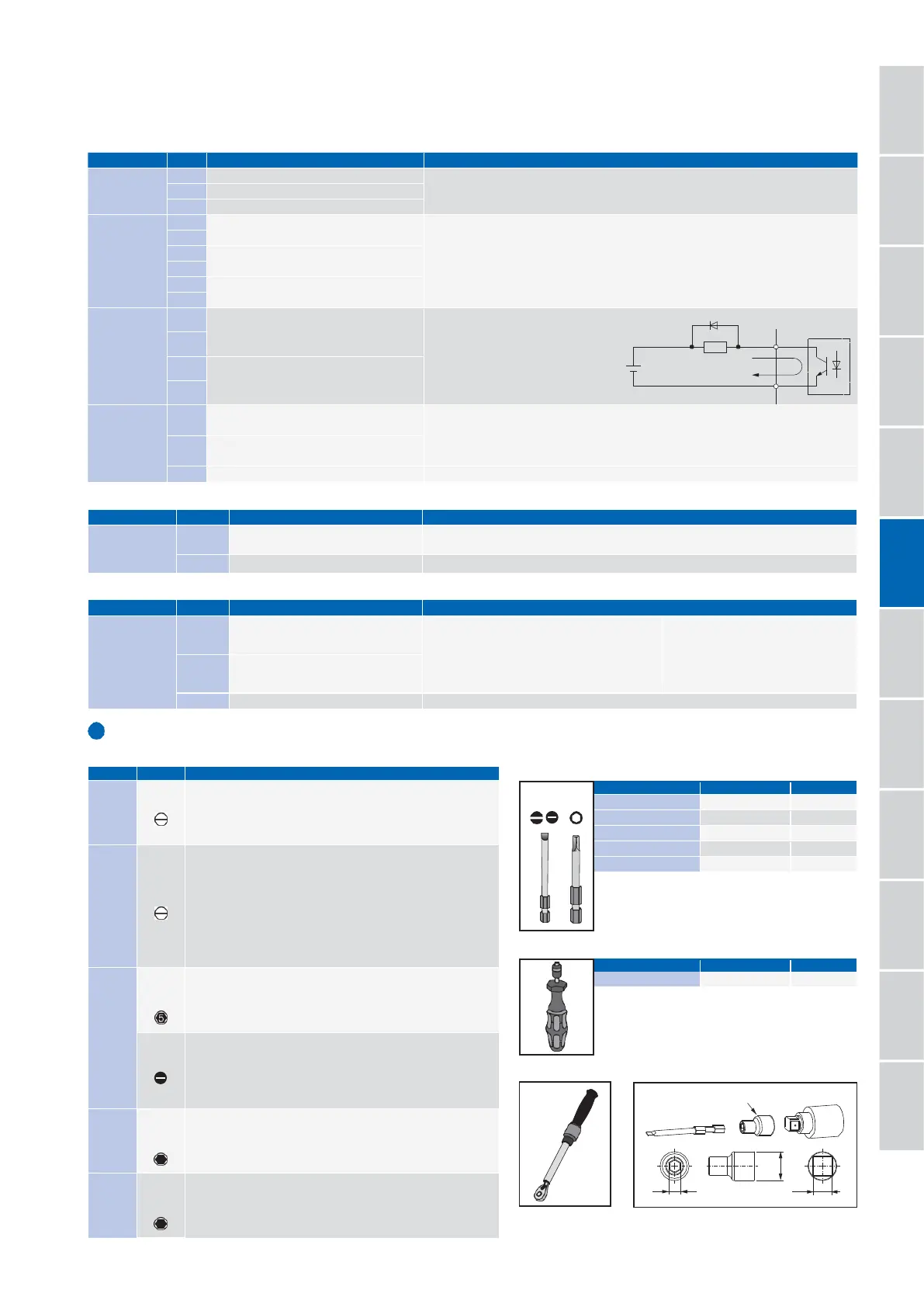
Tools for Wiring European Style Terminal Blocks
(
Recommended product
)
Check the “Terminal size / Wire gauge” on the next page and prepare the tools for wiring.
Bit
Torque screwdriver
Torque wrench Bit socket holder
Terminal Type Terminal
MA
Multi
-
Function
Digital Output
MB
MC
M
1
M
2
M
3
M
4
M
5
M
6
P1
Signal Function
(
default
)
N.O. output
(
Fault
)
N.C. output
(
Fault
)
Digital output common
Multi
-
function digital output
(
Brake Release Command
)
Multi
-
function digital output
(
During run
)
Description
(
Signal Level
)
Multi
-
function digital output
(
Speed agree
1
)
・
Relay output
・
30
Vdc or less,
10
mA to
1
A
・
250
Vac or less,
10
mA to
1
A
・
Minimum load
:
5
Vdc
,
10
mA
(
Values only for reference
)
・
Relay output
・
30
Vdc or less,
10
mA to
1
A
・
250
Vac or less,
10
mA to
1
A
・
Minimum load
:
5
Vdc,
10
mA
(
Values only for reference
)
Note
:
Switching life is estimated at
8
,
000
,
000
times
(
assumes
30
mA, inductive load
)
and
200
,
000
times
(
assumes
1
A, resistive load
)
. When an inductive load such as
relay coils is switched on and off, connecting the surge absorber parallel to the
load is an effective means to protect the contacts.
Multi
-
Function
Photocoupler
Output
Multi
-
Function Photocoupler Output
(
Drive Ready
(
READY
))
Multi
-
Function Photocoupler Output
(
Alarms
)
analog monitor
(
1
) (
Output frequency
)
・
Photocoupler output
・
48
Vdc or less,
2
to
50
mA
Note
:
Connect a flywheel diode
as shown below when
driving a reactive load
such as a relay coil. Diode
must be rated higher
than the circuit voltage.
Voltage output
Monitor
Output AM analog monitor
(
2
) (
Output current
)
AC Monitor common
・
0
to
10
Vdc for
0
to
100
%
・
−
10
to
10
Vdc for
−
100
to
100
%
Note
:
Select the signal level with H
4
-
07
[
Terminal FM Signal Level Select
]
and
H
4
-
08
[
Terminal AM Signal Level Select
]
.
0 V
Fully
-
Enclosed
Design and
Drive
Watt Loss Data
Model Number/
Catalog Code /
Selecting
the Capacity
Peripheral
Devices
and Options
Specifications
Connection
Diagram
Specifications
Prepare the following two tools.
·
Bit
【
PHOENIX CONTACT
】
Model
:
SF
-
BIT
-
SL 1,0X4,0
-
70
·
Torque screwdriver
【
PHOENIX CONTACT
】
Model
:
TSD
-
M
3
NM
(
1
.
2
to
3
N
·
m
)
When wiring drive models CH7
0
A
2047
and CH7
0
A
4075
or earlier
models, be sure to correctly select tools based on the wire gauges.
Wiring Gauge
:
≤ 25 mm
2
or AWG10
·
Bit
【
PHOENIX CONTACT
】
Model
:
SF
-
BIT
-
SL 1,2X6,5
-
70
·
Torque screwdriver
【
PHOENIX CONTACT
】
Model
:
TSD
-
M
3
NM
(
1
.
2
to
3
N
·
m
)
Wiring Gauge
:
≥ 30 mm
2
or AWG8
·
Torque wrench that includes a torque measurement range of 4.5 N·m
·
Bit socket holder of
6
.
35
mm
Prepare the following three tools.
·
Bit
【
PHOENIX CONTACT
】
Model
:
SF
-
BIT
-
HEX
5
-
50
·
Torque wrench that includes a torque measurement range of 9 N·m
·
Bit socket holder of
6
.
35
mm
Prepare the following three tools for the models CH7
0
A
2088
to
2115, and CH70A4091.
·
Bit
【
PHOENIX CONTACT
】
Model
:
SF
-
BIT
-
SL 1,2X6,5
-
70
·
Torque wrench that includes a torque measurement range of
3
.
5
N
·
m
·
Bit socket holder of
6
.
35
mm
Prepare the following three tools.
·
Bit
【
PHOENIX CONTACT
】
Model
:
SF
-
BIT
-
HEX
6
-
50
·
Torque wrench that includes a torque measurement range of 12 N·m
·
Bit socket holder of
6
.
35
mm
Prepare the following three tools.
·
Bit
【
PHOENIX CONTACT
】
Model
:
SF
-
BIT
-
HEX
8
-
50
·
Torque wrench that includes a torque measurement range of 14 N·m
·
Bit socket holder of
6
.
35
mm
 Loading...


