9 Electrical Installation
YASKAWA TOEPC71061723A YASKAWA AC Drive CR700 Quick Start Guide 47
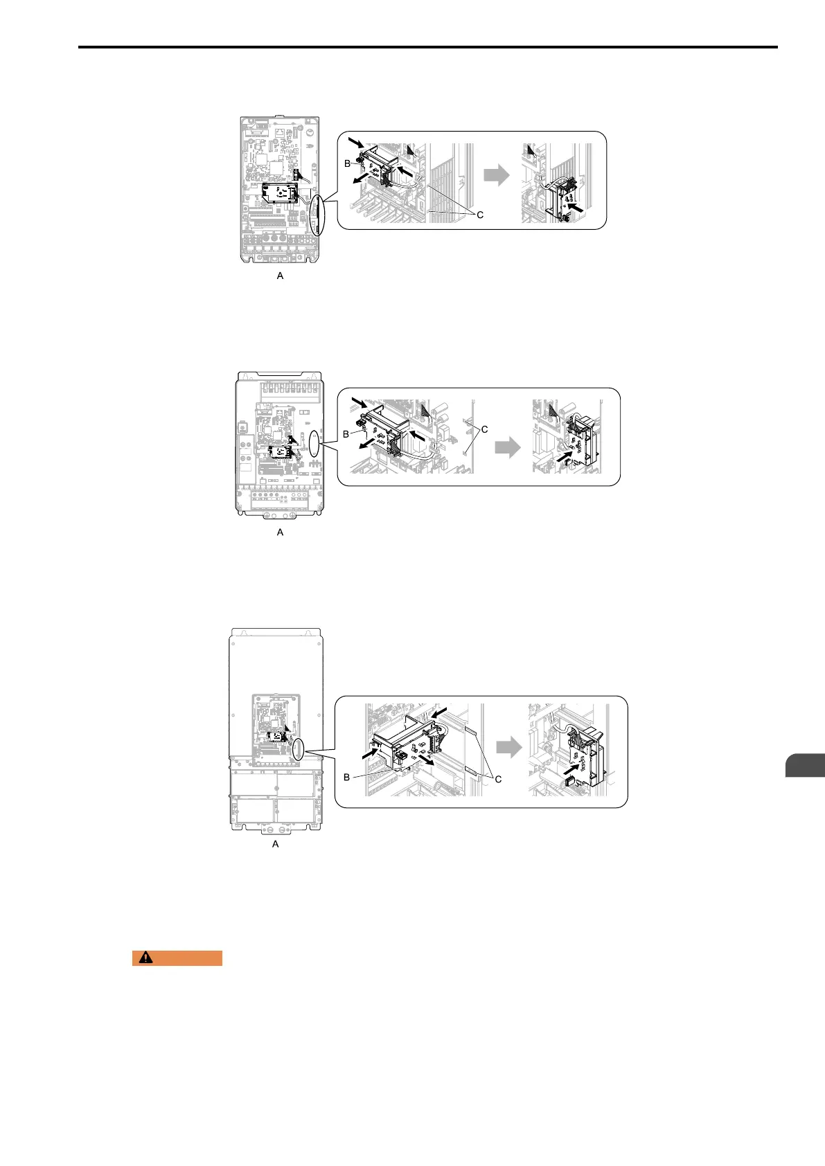
Note:
You can temporarily store the LED status ring board with the temporary placement holes on the drive. The location of the
temporary placement holes is different on different drive models.
A - Drive front
B - LED status ring board
C - Temporary placement holes
Figure 9.22 Remove the LED Status Ring Board
A - Drive front
B - LED status ring board
C - Temporary placement holes
Figure 9.23 Remove the LED Status Ring Board
A - Drive front
B - LED status ring board
C - Temporary placement holes
Figure 9.24 Remove the LED Status Ring Board
2. Refer to the figure and wire the control circuit.
WARNING
Fire Hazard. Tighten all terminal screws to the correct tightening torque. Connections that are too
loose or too tight can cause incorrect operation and damage to the drive. Incorrect connections can also cause death
or serious injury from fire.
Note:
• Use shielded, twisted-pair wires and ground the shield to the ground terminal of the drive. Incorrect equipment grounding
can cause drive or equipment malfunction from electrical interference.
• Do not use control circuit wiring that is longer than 50 m (164 ft) to supply the analog frequency reference from a remote
source. If the control circuit wiring is too long, it can cause unsatisfactory system performance.
EN