4 Installation and Wiring
17
4.2 MECHATROLINK Communications Cables
Wiring
Wire the MECHATROLINK communications cables to the communications connector
(CN2).
• For communications cables, use special shielded twisted-pair cables for MECHATROLINK com-
munications.
Recommended cable: JEPMC-W603- *
* is the length (m).
With USB connector with core
• Install MECHATROLINK communications cables apart from main-circuit wiring and other elec-
trical and power lines
• Connect the terminator (model No.: JEPMC-W6022) on the end of the communication lines.
• Maximum transmission distance is 50 m.
• Minimum wiring distance between stations is 0.5 m.
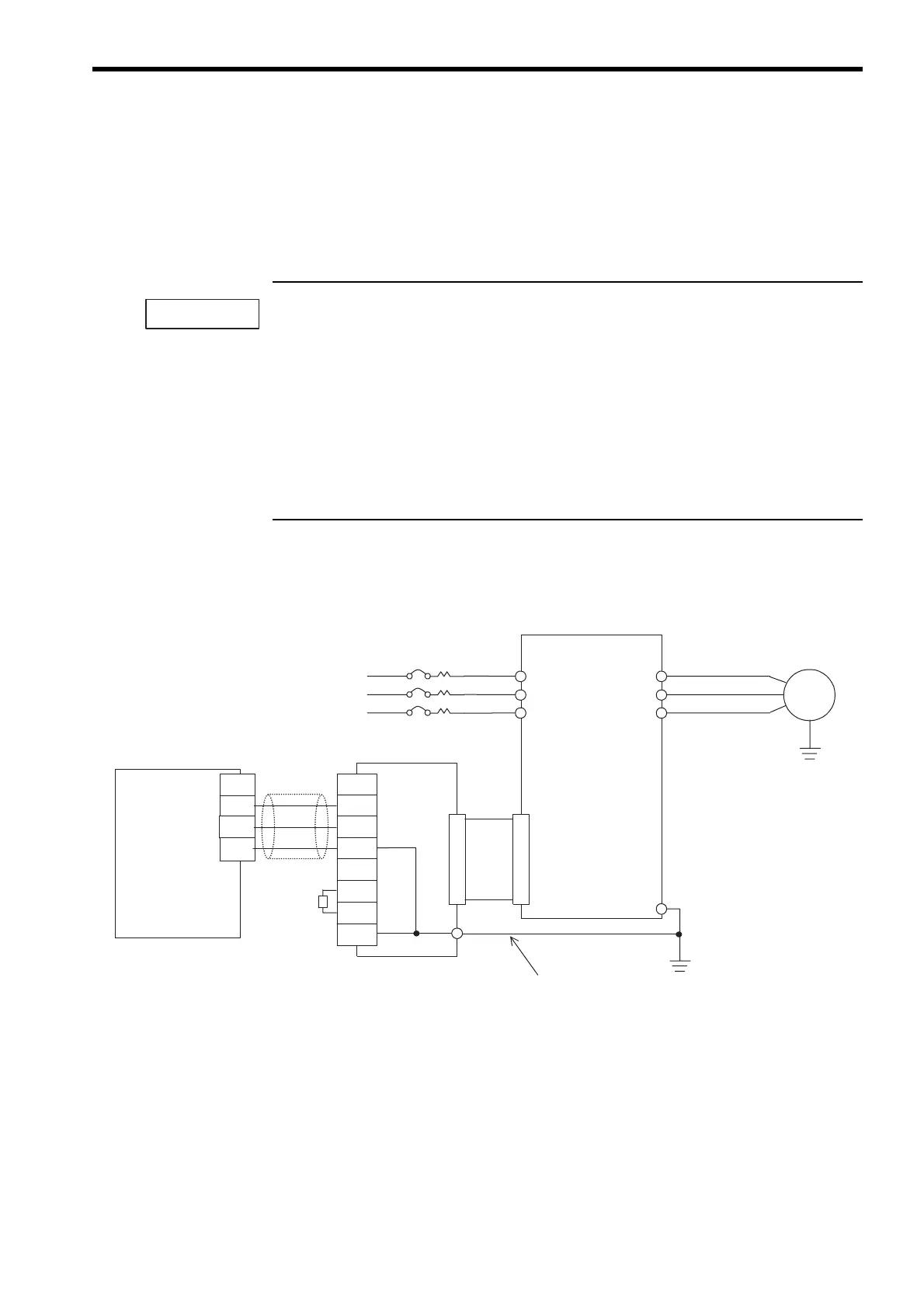
Communications Wiring Example
The following diagram is an example of communications wiring around the Inverters.
Fig. 2 Connection Diagram with Varispeed G7/F7 (3-phase, 200 VAC, 0.4 kW)
IMPORTANT
NC
SRD-
D-
SRD+
SLD
MECHATROLINK
controller
Inverter
3-phase, 200 VAC,
0.4 kW
M
SI-T
3-phase power supply
200 to 230 VAC
R
S
T
U
V
W
E
If there are noise influences on communication,
remove the grounding cable.
*
E
SRD-
SRD+
NC
SLD
SRD-
SRD+
NC
SLD

 Loading...


