44
8 Protective Operations
8.1 Fault Detection Processing
Faults can be detected by two methods: Inverter fault detection and SI-T fault detection.
The SI-T is notified of Inverter faults by the internal interface, and the SI-T sends the
response data, ALARM or STATUS.
The SI-T notifies Inverter of SI-T faults by the internal interface, and the faults are simulta-
neously sent the response data, ALARM or STATUS.
The following four types of faults can be detected. The subsequent operation varies depend-
ing on the type of fault.
Note: The meanings of each symbol are as follows.
−: No change
→: Fault notification to Inverter
←: Fault notification from Inverter
When consecutive alarms occur, the SI-T provides notification of the most recent alarm with
a MECHATROLINK response data. If warnings occur simultaneously, notification priority
is given to the warning with the lowest warning code. If alarms and warnings are mixed
together, the SI-T gives notification priority to alarms.
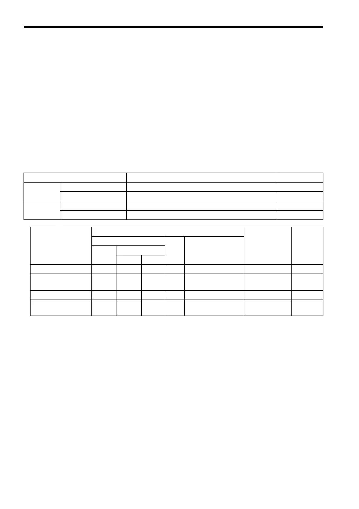
The following table shows the response data when consecutive alarms or warnings occurs.
Fault Type Description Location
Alarm Inverter alarm Major fault that causes damage to the Inverter or machinery Inverter
Communications alarm Interference related to MECHATROLINK-II communications SI-T
Warning Inverter warning Illegal operation or minor fault not posing any immediate danger Inverter
Communications warning MECHATROLINK-II communications fault warning SI-T
Fault Type SI-T Processing Direction of
Communications
Reset
MECHATROLINK Response LED2
Status
Processing
ALARM STATUS
WARNG ALM
Inverter alarm CODE
− 1 −
No special processing
← Required
Communications alarm CODE
− 1Lit
Notification to Inverter
c→
←d
Required
Inverter warning CODE
1 −−
No special processing
← Required
Communications
warning
CODE
1 −−
No special processing
None Not required

 Loading...


